
In antenna theory, a phased array usually means an electronically scanned array, a computer-controlled array of antennas which creates a beam of radio waves that can be electronically steered to point in different directions without moving the antennas.

In the field of antenna design the term radiation pattern refers to the directional (angular) dependence of the strength of the radio waves from the antenna or other source.

A Yagi–Uda antenna or simply Yagi antenna, is a directional antenna consisting of two or more parallel resonant antenna elements in an end-fire array; these elements are most often metal rods acting as half-wave dipoles. Yagi–Uda antennas consist of a single driven element connected to a radio transmitter and/or receiver through a transmission line, and additional "passive radiators" with no electrical connection, usually including one so-called reflector and any number of directors. It was invented in 1926 by Shintaro Uda of Tohoku Imperial University, Japan, with a lesser role played by his colleague Hidetsugu Yagi.

A helical antenna is an antenna consisting of one or more conducting wires wound in the form of a helix. A helical antenna made of one helical wire, the most common type, is called monofilar, while antennas with two or four wires in a helix are called bifilar, or quadrifilar, respectively.

In radio and telecommunications a dipole antenna or doublet is the simplest and most widely used class of antenna. The dipole is any one of a class of antennas producing a radiation pattern approximating that of an elementary electric dipole with a radiating structure supporting a line current so energized that the current has only one node at each end. A dipole antenna commonly consists of two identical conductive elements such as metal wires or rods. The driving current from the transmitter is applied, or for receiving antennas the output signal to the receiver is taken, between the two halves of the antenna. Each side of the feedline to the transmitter or receiver is connected to one of the conductors. This contrasts with a monopole antenna, which consists of a single rod or conductor with one side of the feedline connected to it, and the other side connected to some type of ground. A common example of a dipole is the "rabbit ears" television antenna found on broadcast television sets.

Synthetic-aperture radar (SAR) is a form of radar that is used to create two-dimensional images or three-dimensional reconstructions of objects, such as landscapes. SAR uses the motion of the radar antenna over a target region to provide finer spatial resolution than conventional stationary beam-scanning radars. SAR is typically mounted on a moving platform, such as an aircraft or spacecraft, and has its origins in an advanced form of side looking airborne radar (SLAR). The distance the SAR device travels over a target during the period when the target scene is illuminated creates the large synthetic antenna aperture. Typically, the larger the aperture, the higher the image resolution will be, regardless of whether the aperture is physical or synthetic – this allows SAR to create high-resolution images with comparatively small physical antennas. For a fixed antenna size and orientation, objects which are further away remain illuminated longer - therefore SAR has the property of creating larger synthetic apertures for more distant objects, which results in a consistent spatial resolution over a range of viewing distances.

A sensor array is a group of sensors, usually deployed in a certain geometry pattern, used for collecting and processing electromagnetic or acoustic signals. The advantage of using a sensor array over using a single sensor lies in the fact that an array adds new dimensions to the observation, helping to estimate more parameters and improve the estimation performance. For example an array of radio antenna elements used for beamforming can increase antenna gain in the direction of the signal while decreasing the gain in other directions, i.e., increasing signal-to-noise ratio (SNR) by amplifying the signal coherently. Another example of sensor array application is to estimate the direction of arrival of impinging electromagnetic waves. The related processing method is called array signal processing. A third examples includes chemical sensor arrays, which utilize multiple chemical sensors for fingerprint detection in complex mixtures or sensing environments. Application examples of array signal processing include radar/sonar, wireless communications, seismology, machine condition monitoring, astronomical observations fault diagnosis, etc.
Beamforming or spatial filtering is a signal processing technique used in sensor arrays for directional signal transmission or reception. This is achieved by combining elements in an antenna array in such a way that signals at particular angles experience constructive interference while others experience destructive interference. Beamforming can be used at both the transmitting and receiving ends in order to achieve spatial selectivity. The improvement compared with omnidirectional reception/transmission is known as the directivity of the array.
In electromagnetics and antenna theory, the aperture of an antenna is defined as "A surface, near or on an antenna, on which it is convenient to make assumptions regarding the field values for the purpose of computing fields at external points. NOTE - The aperture is often taken as that portion of a plane surface near the antenna, perpendicular to the direction of maximum radiation, through which the major part of the radiation passes."
Linear discriminant analysis (LDA), normal discriminant analysis (NDA), or discriminant function analysis is a generalization of Fisher's linear discriminant, a method used in statistics and other fields, to find a linear combination of features that characterizes or separates two or more classes of objects or events. The resulting combination may be used as a linear classifier, or, more commonly, for dimensionality reduction before later classification.
Antenna measurement techniques refers to the testing of antennas to ensure that the antenna meets specifications or simply to characterize it. Typical parameters of antennas are gain, bandwidth, radiation pattern, beamwidth, polarization, and impedance.

In electromagnetics, directivity is a parameter of an antenna or optical system which measures the degree to which the radiation emitted is concentrated in a single direction. It is the ratio of the radiation intensity in a given direction from the antenna to the radiation intensity averaged over all directions. Therefore, the directivity of a hypothetical isotropic radiator is 1, or 0 dBi.
Characteristic modes (CM) form a set of functions which, under specific boundary conditions, diagonalizes operator relating field and induced sources. Under certain conditions, the set of the CM is unique and complete and thereby capable of describing the behavior of a studied object in full.
Phase-comparison monopulse is a technique used in radio frequency (RF) applications such as radar and direction finding to accurately estimate the direction of arrival of a signal from the phase difference of the signal measured on two separated antennas or more typically from displaced phase centers of an array antenna. Phase-comparison monopulse differs from amplitude-comparison monopulse in that the former uses displaced phase centers with a common beam pointing direction, while the latter uses a common phase center and displaced beam pointing directions.
In physics, a quantum amplifier is an amplifier that uses quantum mechanical methods to amplify a signal; examples include the active elements of lasers and optical amplifiers.
Leaky-wave antenna (LWA) belong to the more general class of traveling wave antenna, that use a traveling wave on a guiding structure as the main radiating mechanism. Traveling-wave antenna fall into two general categories, slow-wave antennas and fast-wave antennas, which are usually referred to as leaky-wave antennas.
Fresnel zone antennas are antennas that focus the signal by using the phase shifting property of the antenna surface or its shape . There are several types of Fresnel zone antennas, namely, Fresnel zone plate, offset Fresnel zone plate antennas, phase correcting reflective array or "Reflectarray" antennas and 3 Dimensional Fresnel antennas. They are a class of diffractive antennas and have been used from radio frequencies to X rays.
An electrically small or electrically short antenna is an antenna much shorter than the wavelength of the signal it is intended to transmit or receive. Electrically short antennas are generally less efficient and more challenging to design than longer antennas such as quarter- and half-wave antennas, but are nonetheless common due to their compact size and low cost.
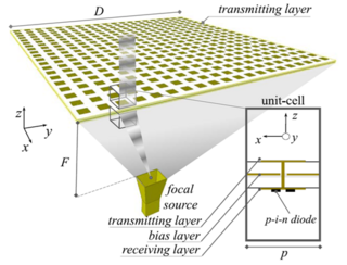
A transmitarray antenna is a phase-shifting surface (PSS), a structure capable of focusing electromagnetic radiation from a source antenna to produce a high-gain beam. Transmitarrays consist of an array of unit cells placed above a source (feeding) antenna. Phase shifts are applied to the unit cells, between elements on the receive and transmit surfaces, to focus the incident wavefronts from the feeding antenna. These thin surfaces can be used instead of a dielectric lens. Unlike phased arrays, transmitarrays do not require a feed network, so losses can be greatly reduced. Similarly, they have an advantage over reflectarrays in that feed blockage is avoided.

For discrete aperture antennas in which the element spacing is greater than a half wavelength, a spatial aliasing effect allows plane waves incident to the array from visible angles other than the desired direction to be coherently added, causing grating lobes. Grating lobes are undesirable and identical to the main lobe. The perceived difference seen in the grating lobes is because of the radiation pattern of non-isotropic antenna elements, which effects main and grating lobes differently. For isotropic antenna elements, the main and grating lobes are identical.


