Related Research Articles

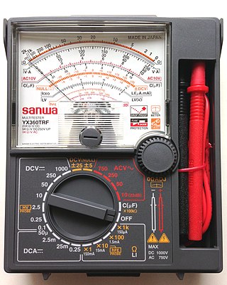
A multimeter is a measuring instrument that can measure multiple electrical properties. A typical multimeter can measure voltage, resistance, and current, in which case can be used as a voltmeter, ohmmeter, and ammeter. Some feature the measurement of additional properties such as temperature and capacitance.
In a hybrid set, hybrid coil, or resistance hybrid, balancing network is a circuit used to match, i.e., to balance, the impedance of a uniform transmission line, over a selected range of frequencies. A balancing network is required to ensure isolation between the two ports of the four-wire side of the hybrid.
In telecommunications, a hybrid balance is an expression of the degree of electrical symmetry between two impedances connected to two conjugate sides of a hybrid coil or resistance hybrid. It is usually expressed in dB.

A hybrid transformer is a type of directional coupler which is designed to be configured as a circuit having four ports that are conjugate in pairs, implemented using one or more transformers. It is a particular case of the more general concept of a hybrid coupler.

In electrical engineering, impedance is the opposition to alternating current presented by the combined effect of resistance and reactance in a circuit.
This is an index of articles relating to electronics and electricity or natural electricity and things that run on electricity and things that use or conduct electricity.

In electronics, a common-base amplifier is one of three basic single-stage bipolar junction transistor (BJT) amplifier topologies, typically used as a current buffer or voltage amplifier.

A balun is an electrical device that allows balanced and unbalanced lines to be interfaced without disturbing the impedance arrangement of either line. A balun can take many forms and may include devices that also transform impedances but need not do so. Sometimes, in the case of transformer baluns, they use magnetic coupling but need not do so. Common-mode chokes are also used as baluns and work by eliminating, rather than rejecting, common mode signals.

In electrical engineering, impedance matching is the practice of designing or adjusting the input impedance or output impedance of an electrical device for a desired value. Often, the desired value is selected to maximize power transfer or minimize signal reflection. For example, impedance matching typically is used to improve power transfer from a radio transmitter via the interconnecting transmission line to the antenna. Signals on a transmission line will be transmitted without reflections if the transmission line is terminated with a matching impedance.

In analog telephony, a telephone hybrid is the component at the ends of a subscriber line of the public switched telephone network (PSTN) that converts between two-wire and four-wire forms of bidirectional audio paths. When used in broadcast facilities to enable the airing of telephone callers, the broadcast-quality telephone hybrid is known as a broadcast telephone hybrid or telephone balance unit.

A zigzag transformer winding is a special-purpose transformer winding with a zigzag or "interconnected star" connection, such that each output is the vector sum of two (2) phases offset by 120°. It is used as a grounding transformer, creating a missing neutral connection from an ungrounded 3-phase system to permit the grounding of that neutral to an earth reference point; to perform harmonic mitigation, as they can suppress triplet harmonic currents; to supply 3-phase power as an autotransformer ; and to supply non-standard, phase-shifted, 3-phase power.
In telecommunication, a two-wire circuit is characterized by supporting transmission in two directions simultaneously, as opposed to four-wire circuits, which have separate pairs for transmit and receive. The subscriber local loop from the telco central office are almost all two wire for analog baseband voice calls, and converted to four-wire at the line card back when telephone switching was performed on baseband audio. Today the audio is digitized and processed completely in the digital domain upstream from the local loop.
The chief electrical characteristic of a dynamic loudspeaker's driver is its electrical impedance as a function of frequency. It can be visualized by plotting it as a graph, called the impedance curve.

A Maxwell bridge is a modification to a Wheatstone bridge used to measure an unknown inductance in terms of calibrated resistance and inductance or resistance and capacitance. When the calibrated components are a parallel resistor and capacitor, the bridge is known as a Maxwell bridge. It is named for James C. Maxwell, who first described it in 1873.

Various types of electrical transformer are made for different purposes. Despite their design differences, the various types employ the same basic principle as discovered in 1831 by Michael Faraday, and share several key functional parts.

Zobel networks are a type of filter section based on the image-impedance design principle. They are named after Otto Zobel of Bell Labs, who published a much-referenced paper on image filters in 1923. The distinguishing feature of Zobel networks is that the input impedance is fixed in the design independently of the transfer function. This characteristic is achieved at the expense of a much higher component count compared to other types of filter sections. The impedance would normally be specified to be constant and purely resistive. For this reason, Zobel networks are also known as constant resistance networks. However, any impedance achievable with discrete components is possible.
In electrical engineering, a balanced circuit is electronic circuitry for use with a balanced line, or the balanced line itself. Balanced lines are a common method of transmitting many types of electrical signals between two points on two wires. In a balanced line, the two signal lines are of a matched impedance to help ensure that interference, induced in the line, is common-mode and can be removed at the receiving end by circuitry with good common-mode rejection. To maintain the balance, circuit blocks which interface to the line or are connected in the line must also be balanced.
Image impedance is a concept used in electronic network design and analysis and most especially in filter design. The term image impedance applies to the impedance seen looking into a port of a network. Usually a two-port network is implied but the concept can be extended to networks with more than two ports. The definition of image impedance for a two-port network is the impedance, Zi 1, seen looking into port 1 when port 2 is terminated with the image impedance, Zi 2, for port 2. In general, the image impedances of ports 1 and 2 will not be equal unless the network is symmetrical with respect to the ports.

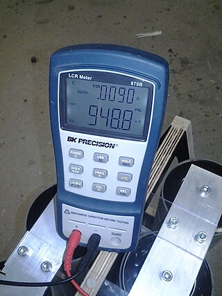
An LCR meter is a type of electronic test equipment used to measure the inductance (L), capacitance (C), and resistance (R) of an electronic component. In the simpler versions of this instrument the impedance was measured internally and converted for display to the corresponding capacitance or inductance value. Readings should be reasonably accurate if the capacitor or inductor device under test does not have a significant resistive component of impedance. More advanced designs measure true inductance or capacitance, as well as the equivalent series resistance of capacitors and the Q factor of inductive components.
Nominal impedance in electrical engineering and audio engineering refers to the approximate designed impedance of an electrical circuit or device. The term is applied in a number of different fields, most often being encountered in respect of:
References
![]() This article incorporates public domain material from Federal Standard 1037C. General Services Administration. Archived from the original on 2022-01-22. (in support of MIL-STD-188).
This article incorporates public domain material from Federal Standard 1037C. General Services Administration. Archived from the original on 2022-01-22. (in support of MIL-STD-188).