
An ammeter is an instrument used to measure the current in a circuit. Electric currents are measured in amperes (A), hence the name. For direct measurement, the ammeter is connected in series with the circuit in which the current is to be measured. An ammeter usually has low resistance so that it does not cause a significant voltage drop in the circuit being measured.

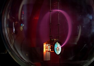
An electric current is a stream of charged particles, such as electrons or ions, moving through an electrical conductor or space. It is measured as the net rate of flow of electric charge through a surface or into a control volume. The moving particles are called charge carriers, which may be one of several types of particles, depending on the conductor. In electric circuits the charge carriers are often electrons moving through a wire. In semiconductors they can be electrons or holes. In an electrolyte the charge carriers are ions, while in plasma, an ionized gas, they are ions and electrons.
The centimetre–gram–second system of units is a variant of the metric system based on the centimetre as the unit of length, the gram as the unit of mass, and the second as the unit of time. All CGS mechanical units are unambiguously derived from these three base units, but there are several different ways in which the CGS system was extended to cover electromagnetism.

Voltage, also known as electric pressure, electric tension, or (electric) potential difference, is the difference in electric potential between two points. In a static electric field, it corresponds to the work needed per unit of charge to move a test charge between the two points. In the International System of Units, the derived unit for voltage is named volt.

The volt is the unit of electric potential, electric potential difference (voltage), and electromotive force in the International System of Units (SI). It is named after the Italian physicist Alessandro Volta (1745–1827).
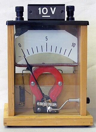
A voltmeter is an instrument used for measuring electric potential difference between two points in an electric circuit. It is connected in parallel. It usually has a high resistance so that it takes negligible current from the circuit.
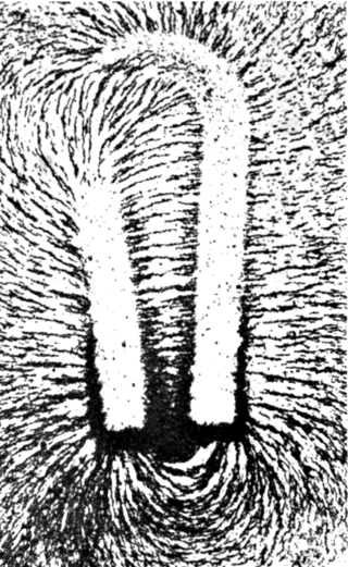
A magnetic field is a vector field that describes the magnetic influence on moving electric charges, electric currents, and magnetic materials. A moving charge in a magnetic field experiences a force perpendicular to its own velocity and to the magnetic field. A permanent magnet's magnetic field pulls on ferromagnetic materials such as iron, and attracts or repels other magnets. In addition, a nonuniform magnetic field exerts minuscule forces on "nonmagnetic" materials by three other magnetic effects: paramagnetism, diamagnetism, and antiferromagnetism, although these forces are usually so small they can only be detected by laboratory equipment. Magnetic fields surround magnetized materials, and are created by electric currents such as those used in electromagnets, and by electric fields varying in time. Since both strength and direction of a magnetic field may vary with location, it is described mathematically by a function assigning a vector to each point of space, called a vector field.

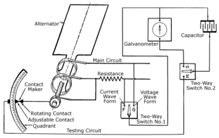
A galvanometer is an electromechanical measuring instrument for electric current. Early galvanometers were uncalibrated, but improved versions, called ammeters, were calibrated and could measure the flow of current more precisely.
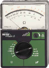
An ohmmeter is an electrical instrument that measures electrical resistance. Multimeters also function as ohmmeters when in resistance-measuring mode. An ohmmeter applies current to the circuit or component whose resistance is to be measured. It then measures the resulting voltage and calculates the resistance using Ohm’s law .
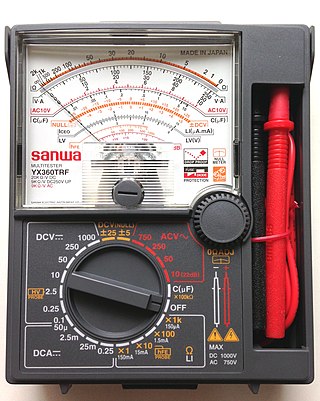
A multimeter is a measuring instrument that can measure multiple electrical properties. A typical multimeter can measure voltage, resistance, and current, in which case can be used as a voltmeter, ammeter, and ohmmeter. Some feature the measurement of additional properties such as temperature and capacitance. The first attested usage of the word "multimeter" listed by the Oxford English Dictionary is from 1907.
In electrical engineering, the power factor of an AC power system is defined as the ratio of the real power absorbed by the load to the apparent power flowing in the circuit. Real power is the average of the instantaneous product of voltage and current and represents the capacity of the electricity for performing work. Apparent power is the product of RMS current and voltage. Due to energy stored in the load and returned to the source, or due to a non-linear load that distorts the wave shape of the current drawn from the source, the apparent power may be greater than the real power, so more current flows in the circuit than would be required to transfer real power alone. A power factor magnitude of less than one indicates the voltage and current are not in phase, reducing the average product of the two. A negative power factor occurs when the device generates real power, which then flows back towards the source.

In electromagnetism and electronics, electromotive force is an energy transfer to an electric circuit per unit of electric charge, measured in volts. Devices called electrical transducers provide an emf by converting other forms of energy into electrical energy. Other electrical equipment also produce an emf, such as batteries, which convert chemical energy, and generators, which convert mechanical energy. This energy conversion is achieved by physical forces applying physical work on electric charges. However, electromotive force itself is not a physical force, and ISO/IEC standards have deprecated the term in favor of source voltage or source tension instead.

Electrostatics is a branch of physics that studies electric charges at rest.

A torsion spring is a spring that works by twisting its end along its axis; that is, a flexible elastic object that stores mechanical energy when it is twisted. When it is twisted, it exerts a torque in the opposite direction, proportional to the amount (angle) it is twisted. There are various types:
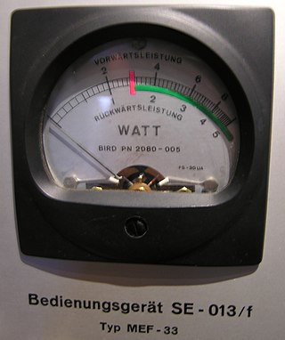
The wattmeter is an instrument for measuring the electric active power in watts of any given circuit. Electromagnetic wattmeters are used for measurement of utility frequency and audio frequency power; other types are required for radio frequency measurements.
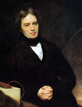
The Faraday paradox or Faraday's paradox is any experiment in which Michael Faraday's law of electromagnetic induction appears to predict an incorrect result. The paradoxes fall into two classes:
The mass-to-charge ratio (m/Q) is a physical quantity relating the mass (quantity of matter) and the electric charge of a given particle, expressed in units of kilograms per coulomb (kg/C). It is most widely used in the electrodynamics of charged particles, e.g. in electron optics and ion optics.
A potentiometer is an instrument for measuring voltage or 'potential difference' by comparison of an unknown voltage with a known reference voltage. If a sensitive indicating instrument is used, very little current is drawn from the source of the unknown voltage. Since the reference voltage can be produced from an accurately calibrated voltage divider, a potentiometer can provide high precision in measurement. The method was described by Johann Christian Poggendorff around 1841 and became a standard laboratory measuring technique.
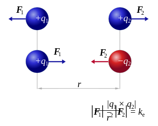
Coulomb's inverse-square law, or simply Coulomb's law, is an experimental law of physics that quantifies the amount of force between two stationary, electrically charged particles. The electric force between charged bodies at rest is conventionally called electrostatic force or Coulomb force. Although the law was known earlier, it was first published in 1785 by French physicist Charles-Augustin de Coulomb, hence the name. Coulomb's law was essential to the development of the theory of electromagnetism, maybe even its starting point, as it made it possible to discuss the quantity of electric charge in a meaningful way.
The history of the oscilloscope was fundamental to science because an oscilloscope is a device for viewing waveform oscillations, as of electrical voltage or current, in order to measure frequency and other wave characteristics. This was important in developing electromagnetic theory. The first recordings of waveforms were with a galvanometer coupled to a mechanical drawing system dating from the second decade of the 19th century. The modern day digital oscilloscope is a consequence of multiple generations of development of the oscillograph, cathode-ray tubes, analog oscilloscopes, and digital electronics.


