Mirror galvanometer

Last updated
Thomson mirror galvanometer of tripod type, from around 1900 Thomson mirror galvanometer.jpg
Thomson mirror galvanometer of tripod type, from around 1900
Galvanometer by H.W. Sullivan, London. Late 19th or early 20th century. This galvanometer was used at the transatlantic cable station, Halifax, NS, Canada H.W.Sullivan Galavanometer London.jpg
Galvanometer by H.W. Sullivan, London. Late 19th or early 20th century. This galvanometer was used at the transatlantic cable station, Halifax, NS, Canada
Modern mirror galvanometer from Scanlab DynAXIS L.jpg
Modern mirror galvanometer from Scanlab

A mirror galvanometer is an ammeter that indicates it has sensed an electric current by deflecting a light beam with a mirror. The beam of light projected on a scale acts as a long massless pointer. In 1826, Johann Christian Poggendorff developed the mirror galvanometer for detecting electric currents. The apparatus is also known as a spot galvanometer after the spot of light produced in some models.

Contents

Mirror galvanometers were used extensively in scientific instruments before reliable, stable electronic amplifiers were available. The most common uses were as recording equipment for seismometers and submarine cables used for telegraphy.

In modern times, the term mirror galvanometer is also used for devices that move laser beams by rotating a mirror through a galvanometer set-up, often with a servo-like control loop. The name is often abbreviated as galvo.

Kelvin's galvanometer

The mirror galvanometer was improved significantly by William Thomson, later to become Lord Kelvin. He coined the term mirror galvanometer and patented the device in 1858. Thomson intended the instrument to read weak signal currents on very long submarine telegraph cables. [1] This instrument was far more sensitive than any which preceded it, enabling the detection of the slightest defect in the core of a cable during its manufacture and submersion.

Thomson decided that he needed an extremely sensitive instrument after he took part in the failed attempt to lay a transatlantic telegraph cable in 1857. He worked on the device while waiting for a new expedition the following year. He first looked at improving a galvanometer used by Hermann von Helmholtz to measure the speed of nerve signals in 1849. Helmholtz's galvanometer had a mirror fixed to the moving needle, which was used to project a beam of light onto the opposite wall, thus greatly amplifying the signal. Thomson intended to make this more sensitive by reducing the mass of the moving parts, but in a flash of inspiration while watching the light reflected from his monocle suspended around his neck, he realised that he could dispense with the needle and its mounting altogether. He instead used a small piece of mirrored glass with a small piece of magnetised steel glued on the back. This was suspended by a thread in the magnetic field of the fixed sensing coil. In a hurry to try the idea, Thomson first used a hair from his dog, but later used a silk thread from the dress of his niece Agnes. [1]

The following is adapted from a contemporary account of Thomson's instrument: [2]

The mirror galvanometer consists of a long fine coil of silk-covered copper wire. In the heart of that coil, within a little air-chamber, a small round mirror is hung by a single fibre of floss silk, with four tiny magnets cemented to its back. A beam of light is thrown from a lamp upon the mirror, and reflected by it upon a white screen or scale a few feet distant, where it forms a bright spot of light. When there is no current on the instrument, the spot of light remains stationary at the zero position on the screen; but the instant a current traverses the long wire of the coil, the suspended magnets twist themselves horizontally out of their former position, the mirror is inclined with them, and the beam of light is deflected along the screen to one side or the other, according to the nature of the current. If a positive electric current gives a deflection to the right of zero, a negative current will give a deflection to the left of zero, and vice versa.

The air in the little chamber surrounding the mirror is compressed at will, so as to act like a cushion, and deaden the movements of the mirror. The needle is thus prevented from idly swinging about at each deflection, and the separate signals are rendered abrupt. At a receiving station the current coming in from the cable has simply to be passed through the coil before it is sent into the ground, and the wandering light spot on the screen faithfully represents all its variations to the clerk, who, looking on, interprets these, and cries out the message word by word. The small weight of the mirror and magnets which form the moving part of this instrument, and the range to which the minute motions of the mirror can be magnified on the screen by the reflected beam of light, which acts as a long impalpable hand or pointer, render the mirror galvanometer marvellously sensitive to the current, especially when compared with other forms of receiving instruments. Messages could be sent from the United Kingdom to the United States through one Atlantic cable and back again through another, and there received on the mirror galvanometer, the electric current used being that from a toy battery made out of a lady's silver thimble, a grain of zinc, and a drop of acidulated water.

The practical advantage of this extreme delicacy is that the signal waves of the current may follow each other so closely as almost entirely to coalesce, leaving only a very slight rise and fall of their crests, like ripples on the surface of a flowing stream, and yet the light spot will respond to each. The main flow of the current will of course shift the zero of the spot, but over and above this change of place the spot will follow the momentary fluctuations of the current which form the individual signals of the message. What with this shifting of the zero and the very slight rise and fall in the current produced by rapid signalling, the ordinary land line instruments are quite unserviceable for work upon long cables.

Moving coil galvanometer

A moving coil galvanometer with its glass cover separated and mirror absent Galvanometro a bobina mobile di Deprez D'Arsonval - Museo scienza tecnologia Milano 10979 01.jpg
A moving coil galvanometer with its glass cover separated and mirror absent

Moving coil galvanometer was developed independently by Marcel Deprez and Jacques-Arsène d'Arsonval about 1880. Deprez's galvanometer was developed for high currents, while D'Arsonval designed his to measure weak currents. Unlike in the Kelvin's galvanometer, in this type of galvanometer the magnet is stationary and the coil is suspended in the magnet gap. The mirror attached to the coil frame rotates together with it. This form of instrument can be more sensitive and accurate and it replaced the Kelvin's galvanometer in most applications. The moving coil galvanometer is practically immune to ambient magnetic fields. Another important feature is self-damping generated by the electro-magnetic forces due to the currents induced in the coil by its movements the magnetic field. These are proportional to the angular velocity of the coil.

Modern uses

Mirror galvo in an RGB laser projector. Laser galvo.jpg
Mirror galvo in an RGB laser projector.
"EdSpot", a popular commercial mirror galvanometer, somewhat resembles this picture. Spot Galvanometer picture.png
"EdSpot", a popular commercial mirror galvanometer, somewhat resembles this picture.

In modern times, high-speed mirror galvanometers are employed in laser light shows to move the laser beams and produce colorful geometric patterns in fog around the audience. Such high speed mirror galvanometers have proved to be indispensable in industry for laser marking systems for everything from laser etching hand tools, containers, and parts to batch-coding semiconductor wafers in semiconductor device fabrication. They typically control X and Y directions on Nd:YAG and CO2 laser markers to control the position of the infrared power laser spot. Laser ablation, laser beam machining and wafer dicing are all industrial areas where high-speed mirror galvanometers can be found.

This moving coil galvanometer is mainly used to measure very feeble or low currents of order 10−9 A.

To linearise the magnetic field across the coil throughout the galvanometer's range of movement, the d'Arsonval design of a soft iron cylinder is placed inside the coil without touching it. This gives a consistent radial field, rather than a parallel linear field.

See also

Related Research Articles

Ammeter Device that measures electric current

An ammeter is a measuring instrument used to measure the current in a circuit. Electric currents are measured in amperes (A), hence the name. The ammeter is usually connected in series with the circuit in which the current is to be measured. An ammeter usually has low resistance so that it does not cause a significant voltage drop in the circuit being measured.

Cathode-ray tube Vacuum tube manipulated to display images on a phosphorescent screen

A cathode-ray tube (CRT) is a vacuum tube containing one or more electron guns, which emit electron beams that are manipulated to display images on a phosphorescent screen. The images may represent electrical waveforms (oscilloscope), pictures, radar targets, or other phenomena. A CRT on a television set is commonly called a picture tube. CRTs have also been used as memory devices, in which case the screen is not intended to be visible to an observer. The term cathode ray was used to describe electron beams when they were first discovered, before it was understood that what was emitted from the cathode was a beam of electrons.

Voltmeter Instrument used for measuring voltage

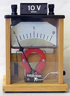
A voltmeter is an instrument used for measuring electric potential difference between two points in an electric circuit. It is connected in parallel. It usually has a high resistance so that it takes negligible current from the circuit.

Electrometer Instrument for measuring electric charge

An electrometer is an electrical instrument for measuring electric charge or electrical potential difference. There are many different types, ranging from historical handmade mechanical instruments to high-precision electronic devices. Modern electrometers based on vacuum tube or solid-state technology can be used to make voltage and charge measurements with very low leakage currents, down to 1 femtoampere. A simpler but related instrument, the electroscope, works on similar principles but only indicates the relative magnitudes of voltages or charges.

Galvanometer Instrument to measure electric current

A galvanometer is an electromechanical measuring instrument for electric current. Early galvanometers were uncalibrated, but improved versions, called ammeters, were calibrated and could measure the flow of current more precisely.

Ohmmeter Tool for measuring electrical resistance

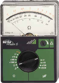
An ohmmeter is an electrical instrument that measures electrical resistance. Multimeters also function as ohmmeters when in resistance-measuring mode. An ohmmeter applies current to the circuit or component whose resistance is to be measured. It then measures the resulting voltage and calculates the resistance using Ohm’s law .

Multimeter Electronic measuring instrument that combines several measurement functions in one unit

A multimeter is a measuring instrument that can measure multiple electrical properties. A typical multimeter can measure voltage, resistance, and current, in which case it is also known as a volt-ohm-milliammeter (VOM), as the unit is equipped with voltmeter, ammeter, and ohmmeter functionality. Some feature the measurement of additional properties such as temperature and capacitance.

Magnetometer Device that measures magnetism

A magnetometer is a device that measures magnetic field or magnetic dipole moment. Different types of magnetometers measure the direction, strength, or relative change of a magnetic field at a particular location. A compass is one such device, one that measures the direction of an ambient magnetic field, in this case, the Earth's magnetic field. Other magnetometers measure the magnetic dipole moment of a magnetic material such as a ferromagnet, for example by recording the effect of this magnetic dipole on the induced current in a coil.

Seismometer Instrument that records seismic waves by measuring ground motions

A seismometer is an instrument that responds to ground noises and shaking such as caused by earthquakes, volcanic eruptions, and explosions. They are usually combined with a timing device and a recording device to form a seismograph. The output of such a device—formerly recorded on paper or film, now recorded and processed digitally—is a seismogram. Such data is used to locate and characterize earthquakes, and to study the Earth's internal structure.

Plasma diagnostics are a pool of methods, instruments, and experimental techniques used to measure properties of a plasma, such as plasma components' density, distribution function over energy (temperature), their spatial profiles and dynamics, which enable to derive plasma parameters.

Degaussing is the process of decreasing or eliminating a remnant magnetic field. It is named after the gauss, a unit of magnetism, which in turn was named after Carl Friedrich Gauss. Due to magnetic hysteresis, it is generally not possible to reduce a magnetic field completely to zero, so degaussing typically induces a very small "known" field referred to as bias. Degaussing was originally applied to reduce ships' magnetic signatures during World War II. Degaussing is also used to reduce magnetic fields in cathode ray tube monitors and to destroy data held on magnetic storage.

Chart recorder

A chart recorder is an electromechanical device that records an electrical or mechanical input trend onto a piece of paper. Chart recorders may record several inputs using different color pens and may record onto strip charts or circular charts. Chart recorders may be entirely mechanical with clockwork mechanisms, electro-mechanical with an electrical clockwork mechanism for driving the chart, or entirely electronic with no mechanical components at all.

Syphon recorder Device used to inscribe telegrams

The syphon or siphon recorder is an obsolete electromechanical device used as a receiver for submarine telegraph cables invented by William Thomson, 1st Baron Kelvin in 1867. It automatically records an incoming telegraph message as a wiggling ink line on a roll of paper tape. Later a trained telegrapher would read the tape, translating the pulses representing the "dots" and "dashes" of the Morse code to characters of the text message.

String galvanometer

A string galvanometer is a sensitive fast-responding measuring instrument that uses a single fine filament of wire suspended in a strong magnetic field to measure small currents. In use, a strong light source is used to illuminate the fine filament, and the optical system magnifies the movement of the filament allowing it to be observed or recorded by photography. The principle of the string galvanometer remained in use for electrocardiograms until the advent of electronic vacuum-tube amplifiers in the 1920s.

Raster scan Rectangular pattern of image capture and reconstruction

A raster scan, or raster scanning, is the rectangular pattern of image capture and reconstruction in television. By analogy, the term is used for raster graphics, the pattern of image storage and transmission used in most computer bitmap image systems. The word raster comes from the Latin word rastrum, which is derived from radere ; see also rastrum, an instrument for drawing musical staff lines. The pattern left by the lines of a rake, when drawn straight, resembles the parallel lines of a raster: this line-by-line scanning is what creates a raster. It is a systematic process of covering the area progressively, one line at a time. Although often a great deal faster, it is similar in the most general sense to how one's gaze travels when one reads lines of text. The data to be drawn is stored in an area of memory called the refresh buffer or frame buffer. This memory area holds the values for each pixel on the screen. These values are retrieved from the refresh buffer and painted onto the screen one row at a time.

Mouse mill motor Simple electric-to-mechanical energy converter

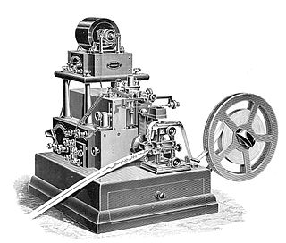
Froment's "mouse mill" motor was an early form of electric motor, also known as the Revolving Armature Engine. It has similarities to both the synchronous motor and the contemporary stepper motor.

History of the oscilloscope


The history of the oscilloscope reaches back to the first recordings of waveforms with a galvanometer coupled to a mechanical drawing system in the second decade of the 19th century. The modern day digital oscilloscope is a consequence of multiple generations of development of the oscillograph, cathode-ray tubes, analog oscilloscopes, and digital electronics.

A vibration galvanometer is a type of mirror galvanometer, usually with a coil suspended in the gap of a magnet or with a permanent magnet suspended in the field of an electromagnet. The natural oscillation frequency of the moving parts is carefully tuned to a specific frequency; commonly 50 or 60 Hz. Higher frequencies up to 1 kHz are possible. Since the frequency depends on the mass of the moving elements, high frequency vibration galvanometers are very small with light coils and mirrors. The tuning of the vibration galvanometer is done by adjusting the tension of the suspension spring.

Ballistic galvanometer

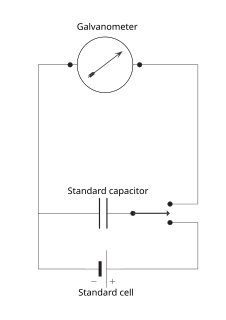
A ballistic galvanometer is a type of sensitive galvanometer; commonly a mirror galvanometer. Unlike a current-measuring galvanometer, the moving part has a large moment of inertia, thus giving it a long oscillation period. It is really an integrator measuring the quantity of charge discharged through it. It can be either of the moving coil or moving magnet type.

Deflection yoke Part of a cathode ray tube which moves the electron beam around

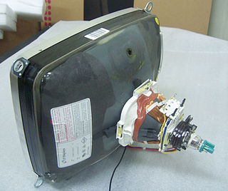
A deflection yoke is a kind of magnetic lens, used in cathode ray tubes to scan the electron beam both vertically and horizontally over the whole screen.

References

  1. 1 2 Lindley, David, Degrees Kelvin: A Tale of Genius, Invention, and Tragedy, pp. 132–133, Joseph Henry Press, 2004 ISBN   0309167825.
  2. Munro, John (July 1997). Heroes of the Telegraph. Project Gutenberg.

Further reading