In press brake forming, the work piece is positioned over a die block and a punch then presses the sheet into the die block to form a shape.[1] Usually bending has to overcome both tensile stresses and compressive stresses. When bending is done, the residual stresses cause the material to spring back towards its original position, so the sheet must be over-bent to achieve the proper bend angle. The amount of spring back is dependent on the material, and the type of forming. When sheet metal is bent, it stretches in length. The bend deduction is the amount the sheet metal will stretch when bent as measured from the outside edges of the bend. The bend radius refers to the inside radius. The formed bend radius is dependent upon the dies used, the material properties, and the material thickness.
The U-punch forms a U-shape with a single punch.[1]
There are three basic types of bending on a press brake, each is defined by the relationship of the end tool position to the thickness of the material. These three are Air Bending, Bottoming and Coining. The configuration of the tools for these three types of bending are nearly identical. A die with a long rail form tool with a radiused tip that locates the inside profile of the bend is called a punch. Punches are usually attached to the ram of the machine by clamps and move to produce the bending force. A die with a long rail form tool that has concave or V-shaped lengthwise channel that locate the outside profile of the form is called a die. Dies are usually stationary and located under the material on the bed of the machine. Note that some locations do not differentiate between the two different kinds of dies (punches and dies). The other types of bending listed use specially designed tools or machines to perform the work.
Air bending
This bending method forms material by pressing a punch (also called the upper or top die) into the material, forcing it into a bottom V-die, which is mounted on the press. The punch forms the bend so that the distance between the punch and the side wall of the V is greater than the material thickness (T).
Either a V-shaped or square opening may be used in the bottom die (dies are frequently referred to as tools or tooling). Because it requires less bend force, air bending tends to use smaller tools than other methods.
Some of the newer bottom tools are adjustable, so, by using a single set of top and bottom tools and varying press-stroke depth, different profiles and products can be produced. Different materials and thicknesses can be bent in varying bend angles, adding the advantage of flexibility to air bending. There are also fewer tool changes, thus, higher productivity.[2]
A disadvantage of air bending is that, because the sheet does not stay in full contact with the dies, it is not as precise as some other methods, and stroke depth must be kept very accurate. Variations in the thickness of the material and wear on the tools can result in defects in parts produced.[2] Thus, the use of adequate process models is important.[3]
Air bending's angle accuracy is approximately ±0.5 deg. Angle accuracy is ensured by applying a value to the width of the V opening, ranging from 6 T (six times material thickness) for sheets to 3mm thick to 12 T for sheets more than 10mm thick. Springback depends on material properties, influencing the resulting bend angle.[2]
Depending on material properties, the sheet may be overbent to compensate for springback.[4]
Air bending does not require the bottom tool to have the same radius as the punch. Bend radius is determined by material elasticity rather than tool shape.[2]
The flexibility and relatively low tonnage required by air bending are helping to make it a popular choice. Quality problems associated with this method are countered by angle-measuring systems, clamps and crowning systems adjustable along the x and y axes, and wear-resistant tools.[2]
The K-factor approximations given below are more likely to be accurate for air bending than the other types of bending due to the lower forces involved in the forming process.
Bottoming
In bottoming, the sheet is forced against the V opening in the bottom tool. U-shaped openings cannot be used. Space is left between the sheet and the bottom of the V opening. The optimum width of the V opening is 6 T (T stands for material thickness) for sheets about 3mm thick, up to about 12 T for 12mm thick sheets. The bending radius must be at least 0.8 T to 2 T for sheet steel. Larger bend radii require about the same force for bottoming as they do for air bending, however, smaller radii require greater force—up to five times as much—than air bending. Advantages of bottoming include greater accuracy and less springback. A disadvantage is that a different tool set is needed for each bend angle, sheet thickness, and material. In general, air bending is the preferred technique.[2]
Coining
In coining, the top tool forces the material into the bottom die with 5 to 30 times the force of air bending, causing permanent deformation through the sheet. There is little, if any, spring back. Coining can produce an inside radius as low as 0.4 T, with a 5 T width of the V opening. While coining can attain high precision, higher costs mean that it is not often used.
Three-point bending
Three-point bending is a newer process that uses a die with an adjustable-height bottom tool, moved by a servo motor. The height can be set within 0.01mm. Adjustments between the ram and the upper tool are made using a hydraulic cushion, which accommodates deviations in sheet thickness. Three-point bending can achieve bend angles with 0.25 deg. precision. While three-point bending permits high flexibility and precision, it also entails high costs and there are fewer tools readily available. It is being used mostly in high-value niche markets.[2]
Folding
In folding, clamping beams hold the longer side of the sheet. The beam rises and folds the sheet around a bend profile. The bend beam can move the sheet up or down, permitting the fabricating of parts with positive and negative bend angles. The resulting bend angle is influenced by the folding angle of the beam, tool geometry, and material properties. Large sheets can be handled in this process, making the operation easily automated. There is little risk of surface damage to the sheet.[2]
Wiping
In wiping, the longest end of the sheet is clamped, then the tool moves up and down, bending the sheet around the bend profile. Though faster than folding, wiping has a higher risk of producing scratches or otherwise damaging the sheet, because the tool is moving over the sheet surface. The risk increases if sharp angles are being produced.[2]
This method will typically bottom or coin the material to set the edge to help overcome springback. In this bending method, the radius of the bottom die determines the final bending radius.
Rotary bending
Rotary bending is similar to wiping but the top die is made of a freely rotating cylinder with the final formed shape cut into it and a matching bottom die. On contact with the sheet, the roll contacts on two points and it rotates as the forming process bends the sheet. This bending method is typically considered a "non-marking" forming process suitable to pre-painted or easily marred surfaces. This bending process can produce angles greater than 90° in a single hit on standard press brakes process.
The roll bending process induces a curve into bar or plate workpieces. There should be proper pre-punching allowance.
Elastomer bending
In this method, the bottom V-die is replaced by a flat pad of urethane or rubber. As the punch forms the part, the urethane deflects and allows the material to form around the punch. This bending method has a number of advantages. The urethane will wrap the material around the punch and the end bend radius will be very close to the actual radius on the punch. It provides a non-marring bend and is suitable for pre-painted or sensitive materials. Using a special punch called a radius ruler with relieved areas on the urethane U-bends greater than 180° can be achieved in one hit, something that is not possible with conventional press tooling. Urethane tooling should be considered a consumable item and while they are not cheap, they are a fraction of the cost of dedicated steel. It also has some drawbacks, this method requires tonnage similar to bottoming and coining and does not do well on flanges that are irregular in shape, that is where the edge of the bent flange is not parallel to the bend and is short enough to engage the urethane pad.
Joggling
A joggle bend in sheet metal (at top of image) and a hand joggling tool
Joggling,[5] also known as joggle bending, is an offset bending process in which two opposite bends with equal angles are formed in a single action creating a small s-shape bend profile and an offset between the unbent face and the result flange that is typically less than 5 material thicknesses.[6] Often the offset will be one material thickness, in order to allow a lap joint where the edge of one sheet of material is laid on top of the other.
Calculations
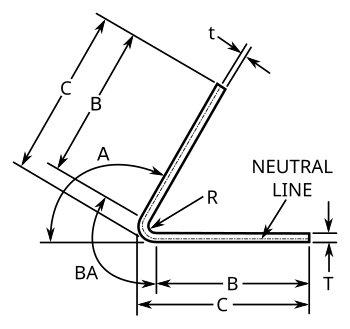
Many variations of these formulas exist and are readily available online. These variations may often seem to be at odds with one another, but they are invariably the same formulas simplified or combined. What is presented here are the unsimplified formulas. All formulas use the following keys:
Lf = flat length of the sheet
BA = bend allowance
BD = bend deduction
R = inside bend radius
K = K-factor, which is t / T
T = material thickness
t = distance from inside face to the neutral line[7]
A = bend angle in degrees (the angle through which the material is bent)
The neutral line (also called the Neutral axis) is an imaginary profile that can be drawn through a cross-section of the workpiece that represents the locus where no tensile or compressivestress are present but shear stresses are at their maximum. In the bend region, the material between the neutral line and the inside radius will be under compression during the bend while the material between the neutral line and the outside radius will be under tension during the bend. Its location in the material is a function of the forces used to form the part and the material yield and tensile strengths. This theoretical definition also coincides with the geometric definition of the plane representing the unbent flat pattern shape within the cross-section of the bent part. Furthermore, the bend allowance (see below) in air bending depends primarily on the width of the opening of the bottom die.[8] As a result, the bending process is more complicated than it appears to be at first sight.
Both bend deduction and bend allowance represent the difference between the neutral line or unbent flat pattern (the required length of the material prior to bending) and the formed bend. Subtracting them from the combined length of both flanges gives the flat pattern length. The question of which to use is determined by the dimensioning method used to define the flanges as shown in the two diagrams below. The flat pattern length is always shorter in length than the sum of all the flange length dimensions due to the geometric transformation. This gives rise to the common perspective that that material is stretching during bending and the bend deduction and bend allowance are the distance that each bend stretches. While a helpful way to look at it, a careful examination of the formulas and stresses involved show this to be false.
The bend allowance (BA) is the length of the arc of the neutral line between the tangent points of a bend in any material. Adding the length of each flange as dimensioned by B in the diagram to the BA gives the Flat Pattern length. This bend allowance formula is used to determine the flat pattern length when a bend is dimensioned from 1) the center of the radius, 2) a tangent point of the radius (B) or 3) the outside tangent point of the radius on an acute angle bend (C). When dimensioned to the outside tangent, the material thickness and bend radius are subtracted from it to find the dimension to the tangent point of the radius before adding in the bend allowance.
The BA can be estimated using the following formula, which incorporates the empirical K-factor:[10]
Angle
90
Pl
3.142
Radius
10.0
K-factor
0.33
Thickness
10
Bend allowance
20.89
Bend deduction
Diagram showing standard dimensioning scheme when using bend deduction formulas
The bend deduction BD is defined as the difference between the sum of the flange lengths (from the edge to the apex) and the initial flat length.
The outside set back (OSSB) is the length from the tangent point of the radius to the apex of the outside of the bend. The bend deduction (BD) is twice the outside setback minus the bend allowance. BD is calculated using the following formula, where A is the angle in radians (=degrees*π/180):[11]
For bends at 90 degrees this formula can be simplified to:
K-factor
K-factor is a ratio of the location of the neutral line to the material thickness as defined by t/T where t = location of the neutral line and T = material thickness. The K-factor formula does not take the forming stresses into account but is simply a geometric calculation of the location of the neutral line after the forces are applied and is thus the roll-up of all the unknown (error) factors for a given setup. The K-factor depends on many variables including the material, the type of bending operation (coining, bottoming, air-bending, etc.) the tools, etc. and is typically between 0.3 and 0.5.
The following equation relates the K-factor to the bend allowance:[12]
The following table is a "rule of thumb". Actual results may vary remarkably.
Generic K-factors
Aluminum
Steel
Radius
Soft materials
Medium materials
Hard materials
Air bending
0 to thickness
0.33
0.38
0.40
Thickness to 3 × thickness
0.40
0.43
0.45
Greater than 3 × thickness
0.50
0.50
0.50
Bottoming
0 to thickness
0.42
0.44
0.46
Thickness to 3 × thickness
0.46
0.47
0.48
Greater than 3 × thickness
0.50
0.50
0.50
Coining
0 to thickness
0.38
0.41
0.44
Thickness to 3 × thickness
0.44
0.46
0.47
Greater than 3 × thickness
0.50
0.50
0.50
The following formula can be used in place of the table as a good approximation of the K-factor for air bending:
Advantages and disadvantages
Bending is a cost-effective near net shape process when used for low to medium quantities. Parts usually are lightweight with good mechanical properties. A disadvantage is that some process variants are sensitive to variations in material properties. For instance, differences in spring-back have a direct influence on the resulting bend angle. To mitigate this, various methods for in-process control have been developed.[13] Other approaches include combining brakeforming with incremental forming.[14]
Broadly speaking, each bend corresponds with a set-up (although sometimes, multiple bends can be formed simultaneously). The relatively large number of set-ups and the geometrical changes during bending make it difficult to address tolerances and bending errors a priori during set-up planning, although some attempts have been made[15]
↑ De Vin, L.J., Streppel, A.H., Singh, U.P. & Kals, H.J.J. A process model for air bending. Journal of Materials Processing Technology, Volume 57, Issues 1–2, 1 February 1996, Pages 48-54 https://doi.org/10.1016/0924-0136(95)02043-8
↑ Tool and Manufacturing Engineers Handbook, Volume 2, Forming, 4th Edition, Society of Manufacturing Engineers, 1984
↑ De Vin, L.J., Expecting the unexpected, a must for accurate brakeforming, Journal of Materials Processing Technology, Volume 117, Issues 1–2, 2 November 2001, Pages 244-248. https://doi.org/10.1016/S0924-0136(01)01140-2
↑ Diegel, Olaf (July 2002), BendWorks(PDF), archived from the original(PDF) on 2010-03-31, retrieved 2010-02-24.
↑ Lutters, D., Streppel, A. H., Kroeze, B. & Kals, H. J. J., Adaptive press brake control in air bending, Proc. of the Shemet97 Conference, Belfast, pp. 471–480, 1997.
This page is based on this Wikipedia article Text is available under the CC BY-SA 4.0 license; additional terms may apply. Images, videos and audio are available under their respective licenses.