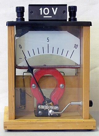
An ammeter is an instrument used to measure the current in a circuit. Electric currents are measured in amperes (A), hence the name. For direct measurement, the ammeter is connected in series with the circuit in which the current is to be measured. An ammeter usually has low resistance so that it does not cause a significant voltage drop in the circuit being measured.

An electric current is a flow of charged particles, such as electrons or ions, moving through an electrical conductor or space. It is defined as the net rate of flow of electric charge through a surface. The moving particles are called charge carriers, which may be one of several types of particles, depending on the conductor. In electric circuits the charge carriers are often electrons moving through a wire. In semiconductors they can be electrons or holes. In an electrolyte the charge carriers are ions, while in plasma, an ionized gas, they are ions and electrons.

The volt is the unit of electric potential, electric potential difference (voltage), and electromotive force in the International System of Units (SI). It is named after the Italian physicist Alessandro Volta (1745–1827).

A voltmeter is an instrument used for measuring electric potential difference between two points in an electric circuit. It is connected in parallel. It usually has a high resistance so that it takes negligible current from the circuit.

Three-phase electric power is a common type of alternating current (AC) used in electricity generation, transmission, and distribution. It is a type of polyphase system employing three wires and is the most common method used by electrical grids worldwide to transfer power.

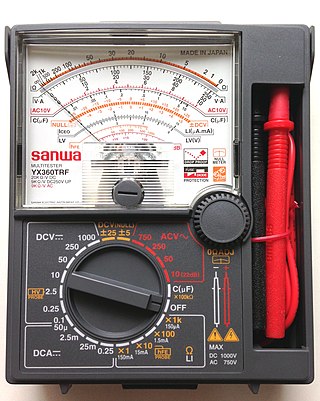
A multimeter is a measuring instrument that can measure multiple electrical properties. A typical multimeter can measure voltage, resistance, and current, in which case can be used as a voltmeter, ammeter, and ohmmeter. Some feature the measurement of additional properties such as temperature and capacitance.
In electrical engineering, the power factor of an AC power system is defined as the ratio of the real power absorbed by the load to the apparent power flowing in the circuit. Real power is the average of the instantaneous product of voltage and current and represents the capacity of the electricity for performing work. Apparent power is the product of RMS current and voltage. Due to energy stored in the load and returned to the source, or due to a non-linear load that distorts the wave shape of the current drawn from the source, the apparent power may be greater than the real power, so more current flows in the circuit than would be required to transfer real power alone. A power factor magnitude of less than one indicates the voltage and current are not in phase, reducing the average product of the two. A negative power factor occurs when the device generates real power, which then flows back towards the source.

Alternating current (AC) is an electric current which periodically reverses direction and changes its magnitude continuously with time, in contrast to direct current (DC), which flows only in one direction. Alternating current is the form in which electric power is delivered to businesses and residences, and it is the form of electrical energy that consumers typically use when they plug kitchen appliances, televisions, fans and electric lamps into a wall socket. A common source of DC power is a battery cell in a flashlight. The abbreviations AC and DC are often used to mean simply alternating and direct, respectively, as when they modify current or voltage.

A split-phase or single-phase three-wire system is a type of single-phase electric power distribution. It is the alternating current (AC) equivalent of the original Edison Machine Works three-wire direct-current system. Its primary advantage is that, for a given capacity of a distribution system, it saves conductor material over a single-ended single-phase system, while only requiring a single phase on the supply side of the distribution transformer.
In electrical engineering, ground and neutral are circuit conductors used in alternating current (AC) electrical systems. The ground circuit is connected to earth, and neutral circuit is usually connected to ground. As the neutral point of an electrical supply system is often connected to earth ground, ground and neutral are closely related. Under certain conditions, a conductor used to connect to a system neutral is also used for grounding (earthing) of equipment and structures. Current carried on a grounding conductor can result in objectionable or dangerous voltages appearing on equipment enclosures, so the installation of grounding conductors and neutral conductors is carefully defined in electrical regulations. Where a neutral conductor is used also to connect equipment enclosures to earth, care must be taken that the neutral conductor never rises to a high voltage with respect to local ground.

An electricity meter, electric meter, electrical meter, energy meter, or kilowatt-hour meter is a device that measures the amount of electric energy consumed by a residence, a business, or an electrically powered device.

High voltage electricity refers to electrical potential large enough to cause injury or damage. In certain industries, high voltage refers to voltage above a certain threshold. Equipment and conductors that carry high voltage warrant special safety requirements and procedures.

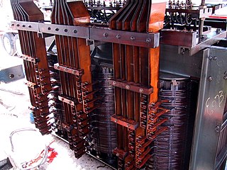
A current transformer (CT) is a type of transformer that is used to reduce or multiply an alternating current (AC). It produces a current in its secondary which is proportional to the current in its primary.

An overhead power line is a structure used in electric power transmission and distribution to transmit electrical energy along large distances. It consists of one or more conductors suspended by towers or poles. Since most of the insulation is provided by air, overhead power lines are generally the lowest-cost method of power transmission for large quantities of electric energy.

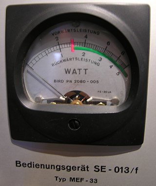
The wattmeter is an instrument for measuring the electric active power in watts of any given circuit. Electromagnetic wattmeters are used for measurement of utility frequency and audio frequency power; other types are required for radio frequency measurements.
An earthing system or grounding system (US) connects specific parts of an electric power system with the ground, typically the Earth's conductive surface, for safety and functional purposes. The choice of earthing system can affect the safety and electromagnetic compatibility of the installation. Regulations for earthing systems vary among countries, though most follow the recommendations of the International Electrotechnical Commission (IEC). Regulations may identify special cases for earthing in mines, in patient care areas, or in hazardous areas of industrial plants.
This is an alphabetical list of articles pertaining specifically to electrical and electronics engineering. For a thematic list, please see List of electrical engineering topics. For a broad overview of engineering, see List of engineering topics. For biographies, see List of engineers.

In electrical and electronic engineering, a current clamp, also known as current probe, is an electrical device with jaws which open to allow clamping around an electrical conductor. This allows measurement of the current in a conductor without the need to make physical contact with it, or to disconnect it for insertion through the probe.

A variety of types of electrical transformer are made for different purposes. Despite their design differences, the various types employ the same basic principle as discovered in 1831 by Michael Faraday, and share several key functional parts.
This glossary of electrical and electronics engineering is a list of definitions of terms and concepts related specifically to electrical engineering and electronics engineering. For terms related to engineering in general, see Glossary of engineering.


