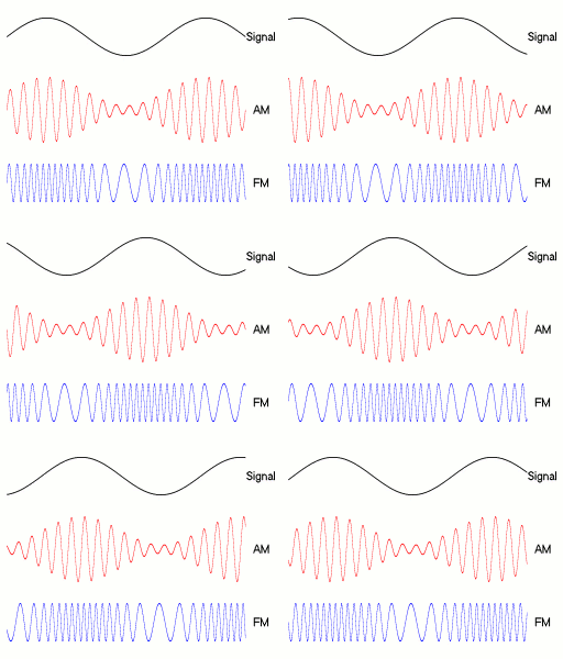
Amplitude modulation (AM) is a modulation technique used in electronic communication, most commonly for transmitting messages with a radio wave. In amplitude modulation, the amplitude of the wave is varied in proportion to that of the message signal, such as an audio signal. This technique contrasts with angle modulation, in which either the frequency of the carrier wave is varied, as in frequency modulation, or its phase, as in phase modulation.

Frequency modulation (FM) is the encoding of information in a carrier wave by varying the instantaneous frequency of the wave. The technology is used in telecommunications, radio broadcasting, signal processing, and computing.
In electronics and telecommunications, modulation is the process of varying one or more properties of a periodic waveform, called the carrier signal, with a separate signal called the modulation signal that typically contains information to be transmitted. For example, the modulation signal might be an audio signal representing sound from a microphone, a video signal representing moving images from a video camera, or a digital signal representing a sequence of binary digits, a bitstream from a computer.
Phase modulation (PM) is a modulation pattern for conditioning communication signals for transmission. It encodes a message signal as variations in the instantaneous phase of a carrier wave. Phase modulation is one of the two principal forms of angle modulation, together with frequency modulation.
Quadrature amplitude modulation (QAM) is the name of a family of digital modulation methods and a related family of analog modulation methods widely used in modern telecommunications to transmit information. It conveys two analog message signals, or two digital bit streams, by changing (modulating) the amplitudes of two carrier waves, using the amplitude-shift keying (ASK) digital modulation scheme or amplitude modulation (AM) analog modulation scheme. The two carrier waves are of the same frequency and are out of phase with each other by 90°, a condition known as orthogonality or quadrature. The transmitted signal is created by adding the two carrier waves together. At the receiver, the two waves can be coherently separated (demodulated) because of their orthogonality. Another key property is that the modulations are low-frequency/low-bandwidth waveforms compared to the carrier frequency, which is known as the narrowband assumption.

In radio communications, single-sideband modulation (SSB) or single-sideband suppressed-carrier modulation (SSB-SC) is a type of modulation used to transmit information, such as an audio signal, by radio waves. A refinement of amplitude modulation, it uses transmitter power and bandwidth more efficiently. Amplitude modulation produces an output signal the bandwidth of which is twice the maximum frequency of the original baseband signal. Single-sideband modulation avoids this bandwidth increase, and the power wasted on a carrier, at the cost of increased device complexity and more difficult tuning at the receiver.
In a radio receiver, the capture effect, or FM capture effect, is a phenomenon associated with FM reception in which only the stronger of two signals at, or near, the same frequency or channel will be demodulated.

An electro-optic modulator (EOM) is an optical device in which a signal-controlled element exhibiting an electro-optic effect is used to modulate a beam of light. The modulation may be imposed on the phase, frequency, amplitude, or polarization of the beam. Modulation bandwidths extending into the gigahertz range are possible with the use of laser-controlled modulators.

Frequency-shift keying (FSK) is a frequency modulation scheme in which digital information is encoded on a carrier signal by periodically shifting the frequency of the carrier between several discrete frequencies. The technology is used for communication systems such as telemetry, weather balloon radiosondes, caller ID, garage door openers, and low frequency radio transmission in the VLF and ELF bands. The simplest FSK is binary FSK, in which the carrier is shifted between two discrete frequencies to transmit binary information.
Phase-shift keying (PSK) is a digital modulation process which conveys data by changing (modulating) the phase of a constant frequency carrier wave. The modulation is accomplished by varying the sine and cosine inputs at a precise time. It is widely used for wireless LANs, RFID and Bluetooth communication.

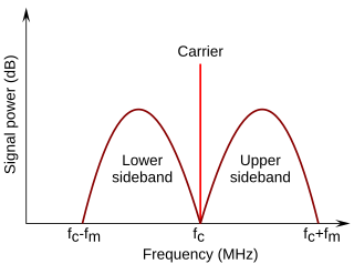
In radio communications, a sideband is a band of frequencies higher than or lower than the carrier frequency, that are the result of the modulation process. The sidebands carry the information transmitted by the radio signal. The sidebands comprise all the spectral components of the modulated signal except the carrier. The signal components above the carrier frequency constitute the upper sideband (USB), and those below the carrier frequency constitute the lower sideband (LSB). All forms of modulation produce sidebands.

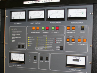
In electronics and telecommunications, a radio transmitter or just transmitter is an electronic device which produces radio waves with an antenna with the purpose of signal transmission up to a radio receiver. The transmitter itself generates a radio frequency alternating current, which is applied to the antenna. When excited by this alternating current, the antenna radiates radio waves.
Demodulation is extracting the original information-bearing signal from a carrier wave. A demodulator is an electronic circuit that is used to recover the information content from the modulated carrier wave. There are many types of modulation so there are many types of demodulators. The signal output from a demodulator may represent sound, images or binary data.
Angle modulation is a class of carrier modulation that is used in telecommunications transmission systems. The class comprises frequency modulation (FM) and phase modulation (PM), and is based on altering the frequency or the phase, respectively, of a carrier signal to encode the message signal. This contrasts with varying the amplitude of the carrier, practiced in amplitude modulation (AM) transmission, the earliest of the major modulation methods used widely in early radio broadcasting.

In electronics, ring modulation is a signal processing function, an implementation of frequency mixing, in which two signals are combined to yield an output signal. One signal, called the carrier, is typically a sine wave or another simple waveform; the other signal is typically more complicated and is called the input or the modulator signal. A ring modulator is an electronic device for ring modulation. A ring modulator may be used in music synthesizers and as an effects unit.

A constellation diagram is a representation of a signal modulated by a digital modulation scheme such as quadrature amplitude modulation or phase-shift keying. It displays the signal as a two-dimensional xy-plane scatter diagram in the complex plane at symbol sampling instants. In a manner similar to that of a phasor diagram, the angle of a point, measured counterclockwise from the horizontal axis, represents the phase shift of the carrier wave from a reference phase; the distance of a point from the origin represents a measure of the amplitude or power of the signal. It could be considered a heat map of I/Q data.

A sinusoid with modulation can be decomposed into, or synthesized from, two amplitude-modulated sinusoids that are in quadrature phase, i.e., with a phase offset of one-quarter cycle. All three sinusoids have the same center frequency. The two amplitude-modulated sinusoids are known as the in-phase (I) and quadrature (Q) components, which describes their relationships with the amplitude- and phase-modulated carrier.

In radio, a detector is a device or circuit that extracts information from a modulated radio frequency current or voltage. The term dates from the first three decades of radio (1888–1918). Unlike modern radio stations which transmit sound on an uninterrupted carrier wave, early radio stations transmitted information by radiotelegraphy. The transmitter was switched on and off to produce long or short periods of radio waves, spelling out text messages in Morse code. Therefore, early radio receivers could reproduce the Morse code "dots" and "dashes" by simply distinguishing between the presence or absence of a radio signal. The device that performed this function in the receiver circuit was called a detector. A variety of different detector devices, such as the coherer, electrolytic detector, magnetic detector and the crystal detector, were used during the wireless telegraphy era until superseded by vacuum tube technology.
In 1933, Edwin H. Armstrong patented a method for generating frequency modulation of radio signals. The Armstrong method generates a double sideband suppressed carrier signal, phase shifts this signal, and then reinserts the carrier to produce a frequency modulated signal.
![]() This article incorporates public domain material from Federal Standard 1037C. General Services Administration. Archived from the original on 2022-01-22. (in support of MIL-STD-188).
This article incorporates public domain material from Federal Standard 1037C. General Services Administration. Archived from the original on 2022-01-22. (in support of MIL-STD-188).


