This article needs additional citations for verification .(December 2009) |

With respect to aircraft performance, a ceiling is the maximum density altitude an aircraft can reach under a set of conditions, as determined by its flight envelope.
This article needs additional citations for verification .(December 2009) |
With respect to aircraft performance, a ceiling is the maximum density altitude an aircraft can reach under a set of conditions, as determined by its flight envelope.
Service ceiling is the density altitude at which the rate of climb drops below a prescribed value.
The service ceiling is the maximum altitude of an aircraft during normal operations. Specifically, it is the density altitude at which flying in a clean configuration, at the best rate of climb airspeed for that altitude and with all engines operating and producing maximum continuous power, will produce a given rate of climb. A typical value might be 100 ft/min (0.51 m/s) climb, [1] or on the order of 500 ft/min (2.5 m/s) climb for jet aircraft.
The one-engine inoperative (OEI) service ceiling of a twin-engine, fixed-wing aircraft is the density altitude at which flying in a clean configuration, at the best rate of climb airspeed for that altitude with one engine producing maximum continuous power and the other engine shut down (and if it has a propeller, the propeller is feathered), will produce a given rate of climb, usually 50 ft/min (0.25 m/s). [2]
However, some performance charts will define the service ceiling as the pressure altitude at which the aircraft will have the capability of climbing at 50 ft/min (0.25 m/s) with one propeller feathered.
Most commercial jetliners have a service (or certified) ceiling of under 45,000 ft (13,700 m) [3] and some business jets about 51,000 ft (15.5 km; 9.7 mi). [4] Before its retirement, the Concorde supersonic transport (SST) (as well as the Tupolev Tu-144 before it was retired) routinely flew at 60,000 ft (18.3 km; 11.4 mi).
The absolute ceiling is the highest altitude at which an aircraft can sustain level flight. Due to the thin air at higher altitudes, a much higher true airspeed (TAS) is required to generate sufficient lift on the wings. The absolute ceiling is therefore the altitude at which the engines are operating at maximum thrust, yet can only generate enough lift to match the weight of the aircraft. Hence, the aircraft will not have any excess capacity to climb further. Stated technically, it is the altitude where the maximum sustained (with no decreasing airspeed) rate of climb is zero.
Compared to service ceiling, the absolute ceiling of commercial aircraft is much higher than for standard operational purposes. In the Concorde's case, it was tested to be 68,000 ft (21 km; 12.9 mi). It is impossible to reach for most (because of the vertical speed asymptotically approaching zero) without afterburners or other devices temporarily increasing thrust. Another factor that makes it impossible for some aircraft to reach their absolute ceiling, even with temporary increases in thrust, is the aircraft reaching the "coffin corner". Flight at the absolute ceiling is also not economically advantageous due to the low indicated airspeed which can be sustained: although the true airspeed at an altitude is typically greater than indicated airspeed (IAS), the difference is not enough to compensate for the fact that IAS at which minimum drag is achieved is usually low, so a flight at an absolute ceiling altitude results in a low TAS as well, and therefore in a high fuel burn rate per distance traveled. The absolute ceiling varies with the air temperature and, overall, the aircraft weight (usually calculated at MTOW). [1]

Flight instruments are the instruments in the cockpit of an aircraft that provide the pilot with data about the flight situation of that aircraft, such as altitude, airspeed, vertical speed, heading and much more other crucial information in flight. They improve safety by allowing the pilot to fly the aircraft in level flight, and make turns, without a reference outside the aircraft such as the horizon. Visual flight rules (VFR) require an airspeed indicator, an altimeter, and a compass or other suitable magnetic direction indicator. Instrument flight rules (IFR) additionally require a gyroscopic pitch-bank, direction and rate of turn indicator, plus a slip-skid indicator, adjustable altimeter, and a clock. Flight into instrument meteorological conditions (IMC) require radio navigation instruments for precise takeoffs and landings.

The airspeed indicator (ASI) or airspeed gauge is a flight instrument indicating the airspeed of an aircraft in kilometres per hour (km/h), knots, miles per hour (MPH) and/or metres per second (m/s). The recommendation by ICAO is to use km/h, however knots (kt) is currently the most used unit. The ASI measures the pressure differential between static pressure from the static port, and total pressure from the pitot tube. This difference in pressure is registered with the ASI pointer on the face of the instrument.

In aerodynamics, wing loading is the total weight of an aircraft or flying animal divided by the area of its wing. The stalling speed, takeoff speed and landing speed of an aircraft are partly determined by its wing loading.

Cruise is the phase of aircraft flight that starts when the aircraft levels off after a climb, until it begins to descend for landing. Cruising usually comprises the majority of a flight, and may include small changes in heading, airspeed, and altitude.

In aviation, airspeed is the speed of an aircraft relative to the air it is flying through. It is difficult to measure the exact airspeed of the aircraft, but other measures of airspeed, such as indicated airspeed and Mach number give useful information about the capabilities and limitations of airplane performance. The common measures of airspeed are:

The true airspeed of an aircraft is the speed of the aircraft relative to the air mass through which it is flying. The true airspeed is important information for accurate navigation of an aircraft. Traditionally it is measured using an analogue TAS indicator, but as GPS has become available for civilian use, the importance of such air-measuring instruments has decreased. Since indicated, as opposed to true, airspeed is a better indicator of margin above the stall, true airspeed is not used for controlling the aircraft; for these purposes the indicated airspeed – IAS or KIAS – is used. However, since indicated airspeed only shows true speed through the air at standard sea level pressure and temperature, a TAS meter is necessary for navigation purposes at cruising altitude in less dense air. The IAS meter reads very nearly the TAS at lower altitude and at lower speed. On jet airliners the TAS meter is usually hidden at speeds below 200 knots (370 km/h). Neither provides for accurate speed over the ground, since surface winds or winds aloft are not taken into account.
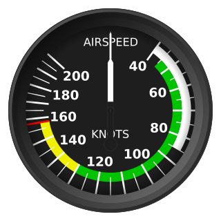
Indicated airspeed (IAS) is the airspeed of an aircraft as measured by its pitot-static system and displayed by the airspeed indicator (ASI). This is the pilots' primary airspeed reference.
Thrust reversal, also called reverse thrust, is the temporary diversion of an aircraft engine's thrust for it to act against the forward travel of the aircraft, providing deceleration. Thrust reverser systems are featured on many jet aircraft to help slow down just after touch-down, reducing wear on the brakes and enabling shorter landing distances. Such devices affect the aircraft significantly and are considered important for safe operations by airlines. There have been accidents involving thrust reversal systems, including fatal ones.
In aeronautics, a descent is any time period during air travel where an aircraft decreases altitude, and is the opposite of an ascent or climb.

The Piper PA-38-112 Tomahawk is a two-seat, fixed tricycle gear general aviation airplane, originally designed for flight training, touring and personal use.

In aeronautics, the rate of climb (RoC) is an aircraft's vertical speed, that is the positive or negative rate of altitude change with respect to time. In most ICAO member countries, even in otherwise metric countries, this is usually expressed in feet per minute (ft/min); elsewhere, it is commonly expressed in metres per second (m/s). The RoC in an aircraft is indicated with a vertical speed indicator (VSI) or instantaneous vertical speed indicator (IVSI).

The Beechcraft 60 Duke is an American-built twin-engine, piston-driven fixed-wing aircraft designed and produced by Beechcraft. The aircraft has retractable tricycle landing gear and a pressurized cabin. The engines are turbocharged, which also pressurize the cabin with bleed air.

The Cessna 441 Conquest II is the first turboprop powered aircraft designed by Cessna and was meant to fill the gap between their jets and piston-engined aircraft. It was developed in November 1974, with the first aircraft delivered in September 1977. It is a pressurized, 8–9 passenger turbine development of the Cessna 404 Titan. The ICAO designator as used in flight plans is C441.
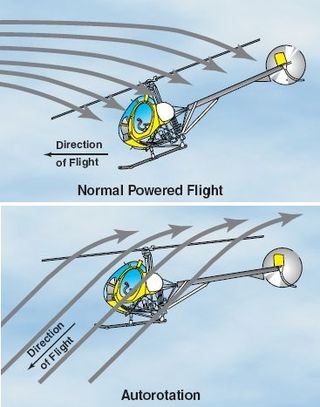
Autorotation is a state of flight in which the main rotor system of a helicopter or other rotary-wing aircraft turns by the action of air moving up through the rotor, as with an autogyro, rather than engine power driving the rotor. The term autorotation dates to a period of early helicopter development between 1915 and 1920, and refers to the rotors turning without the engine. It is analogous to the gliding flight of a fixed-wing aircraft. Some trees have seeds that have wing-like structures that enable the seed to spin to the ground in autorotation, which helps the seeds to disseminate over a wider area.

The Champion 402 Lancer is a twin-engine trainer produced by Champion Aircraft, a high-wing monoplane based on the tricycle gear Champion 7FC Tri-Traveler, but with wing-mounted Continental O-200-A engines. The Lancer first flew in 1961 and production began in 1963. The Lancer seats two in a tandem configuration with dual flight controls; the pilot in command or student pilot normally occupies the front seat.
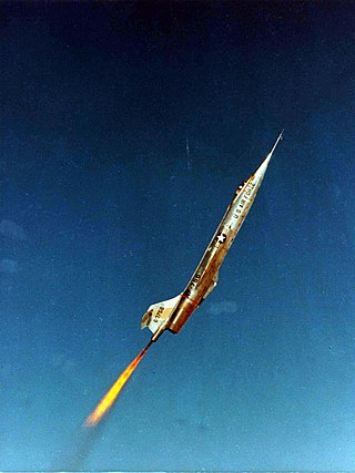
A zoom climb or an unrestricted climb is a maneuver in which the rate of climb is greater than the maximum climb rate using only the thrust of the aircraft's engines. The additional climb rate is attained by reduction of horizontal speed. Before a zoom climb, the aircraft accelerates to a high air speed at an altitude at which it can operate in sustained level flight. The pilot then pulls steeply upward, trading the kinetic energy of forward motion for altitude. This is different from a steady climb, where the increase in potential energy comes from mechanical work done by the engines.

The Junkers Ju 49 was a German aircraft designed to investigate high-altitude flight and the techniques of cabin pressurization. It was the world's second working pressurized aircraft, following the Engineering Division USD-9A which first flew in the United States in 1921. By 1935, it was flying regularly to around 12,500 m (41,000 ft).
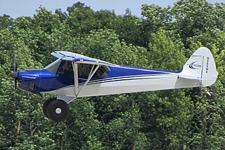
The CubCrafters CC11-160 Carbon Cub SS is an ASTM certified light-sport aircraft based on the Piper J-3 Cub manufactured by Cub Crafters. It is modernized, with light-weight carbon fiber components and a 180 hp (130 kW) engine.
The drag curve or drag polar is the relationship between the drag on an aircraft and other variables, such as lift, the coefficient of lift, angle-of-attack or speed. It may be described by an equation or displayed as a graph. Drag may be expressed as actual drag or the coefficient of drag.
The minimum control speed (VMC) of a multi-engine aircraft is a V-speed that specifies the calibrated airspeed below which directional or lateral control of the aircraft can no longer be maintained, after the failure of one or more engines. The VMC only applies if at least one engine is still operative, and will depend on the stage of flight. Indeed, multiple VMCs have to be calculated for landing, air travel, and ground travel, and there are more still for aircraft with four or more engines. These are all included in the aircraft flight manual of all multi-engine aircraft. When design engineers are sizing an airplane's vertical tail and flight control surfaces, they have to take into account the effect this will have on the airplane's minimum control speeds.