Chip timing

Last updated
A Jaguar Timing System at a finish line using RFID technology with overhead antennas and passive, disposable chips Finish-SprintforSight-Large.jpg
A Jaguar Timing System at a finish line using RFID technology with overhead antennas and passive, disposable chips
A ChronoTrack race controller with RFID antennas for detecting transponders attached to runner's shoes Transponder timing.jpg
A ChronoTrack race controller with RFID antennas for detecting transponders attached to runner's shoes
Runners passing RFID detection mats that are connected to decoders Running mat.jpg
Runners passing RFID detection mats that are connected to decoders
Active chip timing transponder Active transponder.JPG
Active chip timing transponder
ChampionChip 2008 Nike+ Human Race in Taipei the ChampionChip.jpg
ChampionChip

Transponder timing (also called chip timing or RFID timing) is a technique for measuring performance in sport events. A transponder working on a radio-frequency identification (RFID) basis is attached to the athlete and emits a unique code that is detected by radio receivers located at the strategic points in an event.

Contents

Prior to the use of this technology, races were either timed by hand (with operators pressing a stopwatch) or using video camera systems.

Transponder systems

Generally, there are two types of transponder timing systems; active and passive. An active transponder consists of a battery-powered transceiver, connected to the athlete, that emits its unique code when it is interrogated.

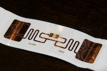
A passive transponder does not contain a power source inside the transponder. Instead, the transponder captures electromagnetic energy produced by a nearby exciter and utilizes that energy to emit a unique code.

In both systems, an antenna is placed at the start, finish, and in some cases, intermediate time points and is connected to a decoder. This decoder identifies the unique transponder code and calculates the exact time when the transponder passes a timing point. Some implementations of timing systems require the use of a mat on the ground at the timing points while other systems implement the timing points with vertically oriented portals.

History

RFID was first used in the late 1980s primarily for motor racing and became more widely adopted in athletic events in the mid-1990s upon the release of low cost 134 kHz transponders and readers from Texas Instruments. This technology formed the basis of electronic sports timing for the world's largest running events as well as for cycling, triathlon and skiing. Some manufacturers made improvements to the technology to handle larger numbers of transponders in the read field or improve the tolerance of their systems to low-frequency noise. These low-frequency systems are still used a lot today. Other manufacturers developed their own proprietary RFID systems usually as an offshoot to more industrial applications. These latter systems attempted to get around the problem of reading large numbers of transponders in a read field by using the High Frequency 13.56 MHz RFID methodology that allowed transponders to use anti-collision algorithms to avoid tags interfering with each other's signal during the down-link between transponder and reader. Active transponder systems continued to mature and despite their much higher cost they retained market share in the high speed sports like motor racing, cycling and ice skating. Active systems are also used at high-profile events such as the Olympics due to their very high read rates and time-stamping precision. By 2005 a newer RFID technology was becoming available, mostly for industrial applications. The first and second generation (UHF) transponders and readers that were being developed followed a strict protocol to ensure that multiple transponders and readers could be used between manufacturers. [1] Much like the HF tags, the UHF tags were much cheaper to produce in volume and formed the basis in the next revolution in sports timing. Currently, many of the largest athletic events are timed using disposable transponders either placed on the back of a race number or on the runner's shoe. The low cost meant that transponders were now fully disposable and did not need to be returned to the organizers after the event.

Usage

Very large running events (more than 10,000) and triathlons were the first events to be transponder (or chip) timed because it is near impossible to manually time them. Also for large runs there are delays in participants reaching the start line, which penalize their performance. Some races place antennas or timing mats at both the start line and the finish line, which allow the exact net time to be calculated. Awards in a race are generally based on the "gun time" (which ignores any delay at the start) as per IAAF and USA Track and Field rules. However, some races use "net time" for presenting age group awards.

In the past the transponder was almost always worn on the athletes running shoe, or on an ankle band. This enabled the transponder to be read best on antenna mats because the distance between the transponder and readers antenna is minimized offering the best capture rate. Transponders may be threaded onto the shoe laces for running. For triathlon a soft elastic ankle band holds the transponder to the leg and care is taken to ensure the transponder is in the correct orientation or polarity for maximum read performance. Transponders have also been placed on the race bib. In the past 5 years[ when? ] the newer UHF systems use transponders placed on the shoe lace, or stuck to the race number bib. In both cases, care must be taken to ensure the UHF tag does not directly touch a large part of the skin as this affects read performance. Despite this, UHF Systems have read performances as good (if not better) than the conventional low and high frequency systems. Because these UHF tags are made in huge volumes for industrial applications, their price is much lower than that of conventional re-usable transponders and the race does not bother to collect them afterwards. As of 2015, many UHF timers use a combination of ground antennas with panel antenna(s) mounted on a tripod at the side of the race course. [2]

A passive tag to be used on the back of the bib Thintag.jpg
A passive tag to be used on the back of the bib
Disposable bib with two passive timing chips at the back Bib with two timing chips.jpg
Disposable bib with two passive timing chips at the back
Back side of disposable RFID tag used for race timing Back side of disposable RFID tag used for race timing.png
Back side of disposable RFID tag used for race timing

All RFID timing systems incorporate a box housing the reader(s) with peripherals like a microprocessor, serial or Ethernet communications and power source (battery). The readers are attached to one or more antennas that are designed for the particular operating frequency. In the case of low or medium frequencies these consist of wire loops incorporated into mats that cover the entire width of the timing point. For UHF systems the antennas consist of patch antennas that are protected in a matting system. The patch antennas may also be placed on stands or a finish gantry pointing towards the oncoming athlete. In most cases the distance between reader and antennas is restricted. Also more equipment is needed for events that require multiple timing points. Wider timing points require more readers and antennas. For active systems a simple wire loop is all that is needed since the transponder has its own power source and the loop serves as a trigger to turn on the transponder, then receive the relatively strong signal from the transponder. Therefore, active systems need less readers (or decoders) per timing point width.

All systems utilize specialized software to calculate results and splits. [3] This software usually resides on a separate PC computer that is connected to the readers via serial or Ethernet communications. The software relates the raw transponder code and timestamp data to each entrant in a database and calculates gun and net times of runners, or the splits of a triathlete. [4] In advanced systems these results are instantly calculated and published to the internet so that athletes and spectators have access to results via any web enabled device.

Related Research Articles

<span class="mw-page-title-main">Transponder</span> Device that emits an identifying signal in response to a received signal

In telecommunications, a transponder is a device that, upon receiving a signal, emits a different signal in response. The term is a blend of transmitter and responder.

<span class="mw-page-title-main">Radio navigation</span> Use of radio-frequency electromagnetic waves to determine position on the Earths surface

Radio navigation or radionavigation is the application of radio frequencies to determine a position of an object on the Earth, either the vessel or an obstruction. Like radiolocation, it is a type of radiodetermination.

Radio-frequency identification (RFID) uses electromagnetic fields to automatically identify and track tags attached to objects. An RFID system consists of a tiny radio transponder, a radio receiver and transmitter. When triggered by an electromagnetic interrogation pulse from a nearby RFID reader device, the tag transmits digital data, usually an identifying inventory number, back to the reader. This number can be used to track inventory goods.

<span class="mw-page-title-main">Distance measuring equipment</span> Radio navigation technology used in aviation

In aviation, distance measuring equipment (DME) is a radio navigation technology that measures the slant range (distance) between an aircraft and a ground station by timing the propagation delay of radio signals in the frequency band between 960 and 1215 megahertz (MHz). Line-of-visibility between the aircraft and ground station is required. An interrogator (airborne) initiates an exchange by transmitting a pulse pair, on an assigned 'channel', to the transponder ground station. The channel assignment specifies the carrier frequency and the spacing between the pulses. After a known delay, the transponder replies by transmitting a pulse pair on a frequency that is offset from the interrogation frequency by 63 MHz and having specified separation.

Floating car data (FCD) in traffic engineering and management is typically timestamped geo-localization and speed data directly collected by moving vehicles, in contrast to traditional traffic data collected at a fixed location by a stationary device or observer. In a physical interpretation context, FCD provides a Lagrangian description of the vehicle movements whereas stationary devices provide an Eulerian description. The participating vehicle acts itself consequently as a moving sensor using an onboard GPS receiver or cellular phone. The most common and widespread use of FCD is to determine the traffic speed on the road network. Based on these data, traffic congestion can be identified, travel times can be calculated, and traffic reports can be rapidly generated. In contrast to stationary devices such as traffic cameras, number plate recognition systems, and induction loops embedded in the roadway, no additional hardware on the road network is necessary.

<span class="mw-page-title-main">EZ TAG</span> Electronic toll collection system in Houston, Texas, United States

EZ TAG is an electronic toll collection system in Houston, Texas, United States, that allows motorists to pay tolls without stopping at toll booths. Motorists with the tags are allowed to use lanes reserved exclusively for them on all Harris County Toll Road Authority (HCTRA) roads. As of late 2003, the EZ TAG can also be used on all lanes of tolled roadways in Texas that accommodate electronic toll collection.

Gee-H, sometimes written G-H or GEE-H, was a radio navigation system developed by Britain during World War II to aid RAF Bomber Command. The name refers to the system's use of the earlier Gee equipment, as well as its use of the "H principle" or "twin-range principle" of location determination. Its official name was AMES Type 100.

ISO 11784 and ISO 11785 are international standards that regulate the radio-frequency identification (RFID) of animals, which is usually accomplished by implanting, introducing or attaching a transponder containing a microchip to an animal.

The clipped tag is a radio frequency identification (RFID) tag designed to enhance consumer privacy. RFID is an identification technology in which information stored in semiconductor chips contained in RFID tags is communicated by means of radio waves to RFID readers. The most simple passive RFID tags do not have batteries or transmitters. They get their energy from the field of the reader. They transfer their information to the reader by modulating the signal that is reflected back to the reader by the tag. Because tags depend on the reader for power their range is limited, typically up to 10 meters (33 ft) for UHF RFID tags.

RuBee is a two-way active wireless protocol designed for harsh environments and high-security asset visibility applications. RuBee utilizes longwave signals to send and receive short data packets in a local regional network. The protocol is similar to the IEEE 802 protocols in that RuBee is networked by using on-demand, peer-to-peer and active radiating transceivers. RuBee is different in that it uses a low frequency carrier. One result is that RuBee is slow compared to other packet-based network data standards (Wi-Fi). 131 kHz as an operating frequency provides RuBee with the advantages of ultra-low power consumption and normal operation near steel and/or water. These features make it easy to deploy sensors, controls, or even actuators and indicators.

Smart Label, also called Smart Tag, is an extremely flat configured transponder under a conventional print-coded label, which includes chip, antenna and bonding wires as a so-called inlay. The labels, made of paper, fabric or plastics, are prepared as a paper roll with the inlays laminated between the rolled carrier and the label media for use in specially-designed printer units.

<span class="mw-page-title-main">Radio</span> Technology of using radio waves to carry information

Radio is the technology of communicating using radio waves. Radio waves are electromagnetic waves of frequency between 3 hertz (Hz) and 300 gigahertz (GHz). They are generated by an electronic device called a transmitter connected to an antenna which radiates the waves. They are received by another antenna connected to a radio receiver. In addition to communication, radio is used for radar, radio navigation, remote control, remote sensing, and other applications.

Deister Electronic is the name generally used to refer to Deister Electronic GmbH Barsinghausen, Germany, and its subsidiaries in North America. Deister Electronic is an industrial enterprise specialised on electronic non-contact identification and security systems founded in 1977. In North America, the companies are Deister Electronics USA, Inc. of Manassas, VA, and Deister Electronics, Inc. of Ontario, Canada.

<span class="mw-page-title-main">Omni-ID</span> American company

Omni-ID is a vendor of passive UHF Radio-frequency identification (RFID) tags. Founded in 2007 as Omni-ID, Ltd., its products are a range of RFID tags designed to operate in all environments, including on metal and liquids.

Real-time locating systems (RTLS), also known as real-time tracking systems, are used to automatically identify and track the location of objects or people in real time, usually within a building or other contained area. Wireless RTLS tags are attached to objects or worn by people, and in most RTLS, fixed reference points receive wireless signals from tags to determine their location. Examples of real-time locating systems include tracking automobiles through an assembly line, locating pallets of merchandise in a warehouse, or finding medical equipment in a hospital.

<span class="mw-page-title-main">Impinj</span>

Impinj, Inc. is a manufacturer of radio-frequency identification (RFID) devices and software. The company was founded in 2000 and is headquartered in Seattle, Washington. The company was started based on the research done at the California Institute of Technology by Carver Mead and Chris Diorio. Impinj currently produces EPC Class 1, Gen 2 passive UHF RFID chips, RFID readers, RFID reader chips, and RFID antennas, and software applications for encoding chips, and gathering business intelligence on RFID systems.

RFID on metal are radio-frequency identification (RFID) tags which perform a specific function when attached to metal objects. The ROM tags overcome some of the problems traditional RFID tags suffer when near metal, such as detuning and reflecting of the RFID signal, which can cause poor tag read range, phantom reads, or no read signal at all.

Chipless RFID tags are RFID tags that do not require a microchip in the transponder.

<span class="mw-page-title-main">Innovative Timing Systems</span>

Innovative Timing Systems (ITS) is a privately held company located in Saint Louis, Missouri which manufactures transponder timing equipment for sports. Its Jaguar system is a Gen 2.0 Radio Frequency Identification (RFID) system operating at ultra high frequencies. Over 500 Jaguar timers use the system to time running, bicycle, motocycle, paddleboard and triathlon events.

<span class="mw-page-title-main">Proxmark3</span>

Proxmark3 is a multi-purpose hardware tool for radio-frequency identification (RFID) security analysis, research and development. It supports both high frequency and low frequency proximity cards and allows users to read, emulate, fuzz, and brute force the majority of RFID protocols.

References

  1. "Class 1 Generation 2 UHF Air Interface Protocol Standard "Gen 2"". Archived from the original on 2015-01-21. Retrieved 2012-12-03.
  2. "Antennas" (PDF). Retrieved 2019-08-08.
  3. Fister, I. Jr., Fister, I., Mernik, M., Brest, J. Design and implementation of domain-specific language Easytime. Computer Languages, Systems & Structures, 37(4), 151-167, 2011. doi : 10.1016/j.cl.2011.04.001
  4. Fister, I. Jr., Mernik, M., Fister, I., Hrnčič, D. Implementation of EasyTime formal semantics using a LISA compiler generator, Comput. Sci. Inf. Syst., vol. 9, no. 3, pp. 1019-1044, 2012. doi : 10.2298/CSIS111110021F