
An operational amplifier is a DC-coupled electronic voltage amplifier with a differential input, a (usually) single-ended output, and an extremely high gain. Its name comes from its original use of performing mathematical operations in analog computers.

In electronics, an analog-to-digital converter is a system that converts an analog signal, such as a sound picked up by a microphone or light entering a digital camera, into a digital signal. An ADC may also provide an isolated measurement such as an electronic device that converts an analog input voltage or current to a digital number representing the magnitude of the voltage or current. Typically the digital output is a two's complement binary number that is proportional to the input, but there are other possibilities.

In electronics, a comparator is a device that compares two voltages or currents and outputs a digital signal indicating which is larger. It has two analog input terminals and and one binary digital output . The output is ideally

Pulse-width modulation (PWM), also known as pulse-duration modulation (PDM) or pulse-length modulation (PLM), is any method of representing a signal as a rectangular wave with a varying duty cycle.

In electronics, a relaxation oscillator is a nonlinear electronic oscillator circuit that produces a nonsinusoidal repetitive output signal, such as a triangle wave or square wave. The circuit consists of a feedback loop containing a switching device such as a transistor, comparator, relay, op amp, or a negative resistance device like a tunnel diode, that repetitively charges a capacitor or inductor through a resistance until it reaches a threshold level, then discharges it again. The period of the oscillator depends on the time constant of the capacitor or inductor circuit. The active device switches abruptly between charging and discharging modes, and thus produces a discontinuously changing repetitive waveform. This contrasts with the other type of electronic oscillator, the harmonic or linear oscillator, which uses an amplifier with feedback to excite resonant oscillations in a resonator, producing a sine wave.

In electronics, a Schmitt trigger is a comparator circuit with hysteresis implemented by applying positive feedback to the noninverting input of a comparator or differential amplifier. It is an active circuit which converts an analog input signal to a digital output signal. The circuit is named a trigger because the output retains its value until the input changes sufficiently to trigger a change. In the non-inverting configuration, when the input is higher than a chosen threshold, the output is high. When the input is below a different (lower) chosen threshold the output is low, and when the input is between the two levels the output retains its value. This dual threshold action is called hysteresis and implies that the Schmitt trigger possesses memory and can act as a bistable multivibrator. There is a close relation between the two kinds of circuits: a Schmitt trigger can be converted into a latch and a latch can be converted into a Schmitt trigger.

The 555 timer IC is an integrated circuit used in a variety of timer, delay, pulse generation, and oscillator applications. It is one of the most popular timing ICs due to its flexibility and price. Derivatives provide two or four timing circuits in one package. The design was first marketed in 1972 by Signetics and used bipolar junction transistors. Since then, numerous companies have made the original timers and later similar low-power CMOS timers. In 2017, it was said that over a billion 555 timers are produced annually by some estimates, and that the design was "probably the most popular integrated circuit ever made".
In electronic instrumentation and signal processing, a time-to-digital converter (TDC) is a device for recognizing events and providing a digital representation of the time they occurred. For example, a TDC might output the time of arrival for each incoming pulse. Some applications wish to measure the time interval between two events rather than some notion of an absolute time.
An integrator in measurement and control applications is an element whose output signal is the time integral of its input signal. It accumulates the input quantity over a defined time to produce a representative output.

Delta-sigma modulation is an oversampling method for encoding signals into low bit depth digital signals at a very high sample-frequency as part of the process of delta-sigma analog-to-digital converters (ADCs) and digital-to-analog converters (DACs). Delta-sigma modulation achieves high quality by utilizing a negative feedback loop during quantization to the lower bit depth that continuously corrects quantization errors and moves quantization noise to higher frequencies well above the original signal's bandwidth. Subsequent low-pass filtering for demodulation easily removes this high frequency noise and time averages to achieve high accuracy in amplitude which can be ultimately encoded as pulse-code modulation (PCM).

A class-D amplifier or switching amplifier is an electronic amplifier in which the amplifying devices operate as electronic switches, and not as linear gain devices as in other amplifiers. They operate by rapidly switching back and forth between the supply rails, using pulse-width modulation, pulse-density modulation, or related techniques to produce a pulse train output. A simple low-pass filter may be used to attenuate their high-frequency content to provide analog output current and voltage. Little energy is dissipated in the amplifying transistors because they are always either fully on or fully off, so efficiency can exceed 90%.
This article illustrates some typical operational amplifier applications. A non-ideal operational amplifier's equivalent circuit has a finite input impedance, a non-zero output impedance, and a finite gain. A real op-amp has a number of non-ideal features as shown in the diagram, but here a simplified schematic notation is used, many details such as device selection and power supply connections are not shown. Operational amplifiers are optimised for use with negative feedback, and this article discusses only negative-feedback applications. When positive feedback is required, a comparator is usually more appropriate. See Comparator applications for further information.

A charge amplifier is an electronic current integrator that produces a voltage output proportional to the integrated value of the input current, or the total charge injected.
A flash ADC is a type of analog-to-digital converter that uses a linear voltage ladder with a comparator at each "rung" of the ladder to compare the input voltage to successive reference voltages. Often these reference ladders are constructed of many resistors; however, modern implementations show that capacitive voltage division is also possible. The output of these comparators is generally fed into a digital encoder, which converts the inputs into a binary value.

Time-of-flight mass spectrometry (TOFMS) is a method of mass spectrometry in which an ion's mass-to-charge ratio is determined by a time of flight measurement. Ions are accelerated by an electric field of known strength. This acceleration results in an ion having the same kinetic energy as any other ion that has the same charge. The velocity of the ion depends on the mass-to-charge ratio. The time that it subsequently takes for the ion to reach a detector at a known distance is measured. This time will depend on the velocity of the ion, and therefore is a measure of its mass-to-charge ratio. From this ratio and known experimental parameters, one can identify the ion.

An oscilloscope is a type of electronic test instrument that graphically displays varying voltages of one or more signals as a function of time. Their main purpose is capturing information on electrical signals for debugging, analysis, or characterization. The displayed waveform can then be analyzed for properties such as amplitude, frequency, rise time, time interval, distortion, and others. Originally, calculation of these values required manually measuring the waveform against the scales built into the screen of the instrument. Modern digital instruments may calculate and display these properties directly.
An integrating ADC is a type of analog-to-digital converter that converts an unknown input voltage into a digital representation through the use of an integrator. In its basic implementation, the dual-slope converter, the unknown input voltage is applied to the input of the integrator and allowed to ramp for a fixed time period. Then a known reference voltage of opposite polarity is applied to the integrator and is allowed to ramp until the integrator output returns to zero. The input voltage is computed as a function of the reference voltage, the constant run-up time period, and the measured run-down time period. The run-down time measurement is usually made in units of the converter's clock, so longer integration times allow for higher resolutions. Likewise, the speed of the converter can be improved by sacrificing resolution.
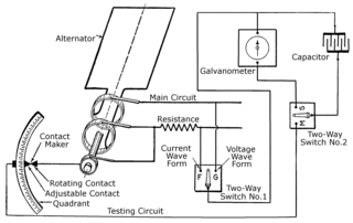
The history of the oscilloscope was fundamental to science because an oscilloscope is a device for viewing waveform oscillations, as of electrical voltage or current, in order to measure frequency and other wave characteristics. This was important in developing electromagnetic theory. The first recordings of waveforms were with a galvanometer coupled to a mechanical drawing system dating from the second decade of the 19th century. The modern day digital oscilloscope is a consequence of multiple generations of development of the oscillograph, cathode-ray tubes, analog oscilloscopes, and digital electronics.
The following outline is provided as an overview of and topical guide to electronics:
A comparator is an electronic component that compares two input voltages. Comparators are closely related to operational amplifiers, but a comparator is designed to operate with positive feedback and with its output saturated at one power rail or the other. If necessary, an op-amp can be pressed into service as a poorly performing comparator, but its slew Rate will be impaired.


