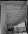
Cross bracing

Last updated
Cross bracing between joists or rafters strengthens the members by preventing sideways deflection. This bracing is known by many names such as herringbone strutting, blocking, bridging, and dwanging. Detail of underside of canopy east side showing cross bracing, rafters, and decking - Fort Hood, World War II Temporary Buildings, Cold Storage Building, Seventeenth Street, HABS TEX,50-KILL.V,1C-14.tif
Cross bracing between joists or rafters strengthens the members by preventing sideways deflection. This bracing is known by many names such as herringbone strutting, blocking, bridging, and dwanging.
Cross bracing on a bridge tower DETAIL VIEW OF TOWER SHOWING CROSS BRACING AND RIVETS - San Francisco Oakland Bay Bridge, Spanning San Francisco Bay, San Francisco, San Francisco County, CA HAER CAL,38-SANFRA,141-14.tif
Cross bracing on a bridge tower

In construction, cross bracing is a system utilized to reinforce building structures in which diagonal supports intersect. Cross bracing is usually seen with two diagonal supports placed in an X-shaped manner. Under lateral force (such as wind or seismic activity) one brace will be under tension while the other is being compressed. In steel construction, steel cables may be used due to their great resistance to tension (although they cannot take any load in compression). The common uses for cross bracing include bridge (side) supports, along with structural foundations. This method of construction maximizes the weight of the load a structure is able to support. It is a usual application when constructing earthquake-safe buildings. [1]

Cross bracing can be applied to any rectangular frame structure, such as chairs and bookshelves. Its rigidity for two-dimensional grid structures can be analyzed mathematically as an instance of the grid bracing problem.

Cross bracing may employ full diagonals, or corner bracing [2] or knee bracing.

The idea of cross bracing is also applied to sport ram-air parachutes to improve their structural integrity. [3]

Mining tunnels

To add rigidity to the construction of mining tunnels, the cross-beam connecting between arches is also a type of cross brace. They are often tubular and modified on the ends with clips or apertures for screw fastening. They serve as a stiffening element for the stability of a design. This brace could also be an ordinary cross-section wooden cross-beam, or even a board.

Cross bracing can be seen in situations like flooring, where cross braces are put between floor joists in order to prevent movement. It is also commonly used for ship making in order to stand against heavy winds or extreme weather.

Related Research Articles

<span class="mw-page-title-main">Structural engineering</span> Sub-discipline of civil engineering dealing with the creation of man made structures

Structural engineering is a sub-discipline of civil engineering in which structural engineers are trained to design the 'bones and muscles' that create the form and shape of human-made structures. Structural engineers also must understand and calculate the stability, strength, rigidity and earthquake-susceptibility of built structures for buildings and nonbuilding structures. The structural designs are integrated with those of other designers such as architects and building services engineer and often supervise the construction of projects by contractors on site. They can also be involved in the design of machinery, medical equipment, and vehicles where structural integrity affects functioning and safety. See glossary of structural engineering.

Brace(s) or bracing may refer to:

<span class="mw-page-title-main">Truss</span> Rigid structure that consists of two-force members only

A truss is an assembly of members such as beams, connected by nodes, that creates a rigid structure.

<span class="mw-page-title-main">Beam (structure)</span> Structural element capable of withstanding loads by resisting bending

A beam is a structural element that primarily resists loads applied laterally to the beam's axis. Its mode of deflection is primarily by bending. The loads applied to the beam result in reaction forces at the beam's support points. The total effect of all the forces acting on the beam is to produce shear forces and bending moments within the beams, that in turn induce internal stresses, strains and deflections of the beam. Beams are characterized by their manner of support, profile, equilibrium conditions, length, and their material.

<span class="mw-page-title-main">Seismic retrofit</span> Modification of existing structures to make them more resistant to seismic activity

Seismic retrofitting is the modification of existing structures to make them more resistant to seismic activity, ground motion, or soil failure due to earthquakes. With better understanding of seismic demand on structures and with our recent experiences with large earthquakes near urban centers, the need of seismic retrofitting is well acknowledged. Prior to the introduction of modern seismic codes in the late 1960s for developed countries and late 1970s for many other parts of the world, many structures were designed without adequate detailing and reinforcement for seismic protection. In view of the imminent problem, various research work has been carried out. State-of-the-art technical guidelines for seismic assessment, retrofit and rehabilitation have been published around the world – such as the ASCE-SEI 41 and the New Zealand Society for Earthquake Engineering (NZSEE)'s guidelines. These codes must be regularly updated; the 1994 Northridge earthquake brought to light the brittleness of welded steel frames, for example.

<span class="mw-page-title-main">Guy-wire</span> Tensioned cable designed to add stability to a freestanding structure

A guy-wire, guy-line, guy-rope, down guy, or stay, also called simply a guy, is a tensioned cable designed to add stability to a free-standing structure. They are used commonly for ship masts, radio masts, wind turbines, utility poles, and tents. A thin vertical mast supported by guy wires is called a guyed mast. Structures that support antennas are frequently of a lattice construction and are called "towers". One end of the guy is attached to the structure, and the other is anchored to the ground at some distance from the mast or tower base. The tension in the diagonal guy-wire, combined with the compression and buckling strength of the structure, allows the structure to withstand lateral loads such as wind or the weight of cantilevered structures. They are installed radially, usually at equal angles about the structure, in trios and quads. As the tower leans a bit due to the wind force, the increased guy tension is resolved into a compression force in the tower or mast and a lateral force that resists the wind load. For example, antenna masts are often held up by three guy-wires at 120° angles. Structures with predictable lateral loads, such as electrical utility poles, may require only a single guy-wire to offset the lateral pull of the electrical wires, at a spot where the wires change direction.

<span class="mw-page-title-main">Shear wall</span> A wall intended to withstand the lateral load

In structural engineering, a shear wall is a two-dimensional vertical element of a system that is designed to resist in-plane lateral forces, typically wind and seismic loads.

<span class="mw-page-title-main">Framing (construction)</span> Construction technique

Framing, in construction, is the fitting together of pieces to give a structure support and shape. Framing materials are usually wood, engineered wood, or structural steel. The alternative to framed construction is generally called mass wall construction, where horizontal layers of stacked materials such as log building, masonry, rammed earth, adobe, etc. are used without framing.

A tie, strap, tie rod, eyebar, guy-wire, suspension cables, or wire ropes, are examples of linear structural components designed to resist tension. It is the opposite of a strut or column, which is designed to resist compression. Ties may be made of any tension resisting material.

<span class="mw-page-title-main">Steel frame</span> Building technique using skeleton frames of vertical steel columns

Steel frame is a building technique with a "skeleton frame" of vertical steel columns and horizontal I-beams, constructed in a rectangular grid to support the floors, roof and walls of a building which are all attached to the frame. The development of this technique made the construction of the skyscraper possible.

The term structural system or structural frame in structural engineering refers to the load-resisting sub-system of a building or object. The structural system transfers loads through interconnected elements or members.

<span class="mw-page-title-main">Structural steel</span> Type of steel used in construction

Structural steel is a category of steel used for making construction materials in a variety of shapes. Many structural steel shapes take the form of an elongated beam having a profile of a specific cross section. Structural steel shapes, sizes, chemical composition, mechanical properties such as strengths, storage practices, etc., are regulated by standards in most industrialized countries.

Steel Design, or more specifically, Structural Steel Design, is an area of structural engineering used to design steel structures. These structures include schools, houses, bridges, commercial centers, tall buildings, warehouses, aircraft, ships and stadiums. The design and use of steel frames are commonly employed in the design of steel structures. More advanced structures include steel plates and shells.

<span class="mw-page-title-main">Howe truss</span>

A Howe truss is a truss bridge consisting of chords, verticals, and diagonals whose vertical members are in tension and whose diagonal members are in compression. The Howe truss was invented by William Howe in 1840, and was widely used as a bridge in the mid to late 1800s.

<span class="mw-page-title-main">Steel plate shear wall</span>

A steel plate shear wall (SPSW) consists of steel infill plates bounded by boundary elements.

A buckling-restrained brace (BRB) is a structural brace in a building, designed to allow the building to withstand cyclical lateral loadings, typically earthquake-induced loading. It consists of a slender steel core, a concrete casing designed to continuously support the core and prevent buckling under axial compression, and an interface region that prevents undesired interactions between the two. Braced frames that use BRBs – known as buckling-restrained braced frames, or BRBFs – have significant advantages over typical braced frames.

<span class="mw-page-title-main">Hybrid masonry</span>

Hybrid masonry is a new type of building system that uses engineered, reinforced masonry to brace frame structures. Typically, hybrid masonry is implemented with concrete masonry panels used to brace steel frame structures. The basic concept is to attach a reinforced concrete masonry panel to a structural steel frame such that some combination of gravity forces, story shears and overturning moments can be transferred to the masonry. The structural engineer can choose from three different types of hybrid masonry and two different reinforcement anchorage types. In conventional steel frame building systems, the vertical force resisting steel frame system is supported in the lateral direction by steel bracing or an equivalent system. When the architectural plans call for concrete masonry walls to be placed within the frame, extra labor is required to ensure the masonry fits around the steel frame. Usually, this placement does not take advantage of the structural properties of the masonry panels. In hybrid masonry, the masonry panels take the place of conventional steel bracing, utilizing the structural properties of reinforced concrete masonry walls.

In aeronautics, bracing comprises additional structural members which stiffen the functional airframe to give it rigidity and strength under load. Bracing may be applied both internally and externally, and may take the form of struts, which act in compression or tension as the need arises, and/or wires, which act only in tension.

This glossary of structural engineering terms pertains specifically to structural engineering and its sub-disciplines. Please see glossary of engineering for a broad overview of the major concepts of engineering.

In the mathematics of structural rigidity, grid bracing is a problem of adding cross bracing to a square grid to make it into a rigid structure. It can be solved optimally by translating it into a problem in graph theory on the connectivity of bipartite graphs.

References

  1. Reinforce Building With Cross Bracing, Earthquake Handbook, FEMA Hazard Mitigation Handbook Series, Federal Emergency Management Agency, 2002.
  2. Tuomi, Roger L.; Gromala, David S. (1977). Racking Strength of Walls: Let-in Corner Bracing, Sheet Materials, and Effect of Loading Rate (PDF) (Report). USDA Forest Service Research Paper.
  3. "Choosing a Canopy". www.uspa.org. Retrieved 2023-08-31.