Structural support

Last updated

A structural support is a part of a building or structure that provides the necessary stiffness and strength in order to resist the internal forces (vertical forces of gravity and lateral forces due to wind and earthquakes) and guide them safely to the ground. External loads (actions of other bodies) that act on buildings cause internal forces (forces and couples by the rest of the structure) in building support structures. Supports can be either at the end or at any intermediate point along a structural member or a constituent part of a building and they are referred to as connections, joints or restraints. [1]

Contents

Building support structures, no matter what materials are used, have to give accurate and safe results. A structure depends less on the weight and stiffness of a material and more on its geometry for stability. [2] Whatever the condition is, a specific rigidity is necessary for connection designs. The support connection type has effects on the load bearing capacity of each element, which makes up a structural system. Each support condition influences the behaviour of the elements and therefore, the system. Structures can be either Horizontal-span support systems (floor and roof structures) or Vertical building structure systems (walls, frames, cores, etc.) [3]

Structure

Structure is necessary for buildings but architecture, as an idea, does not require structure. Every building has both load-bearing structures and non-load bearing portions. Structural members form systems and transfer the loads that are acting upon the structural systems, through a series of elements to the ground. Building Structure Elements include Line (beams, columns, cables, frames or arches, space frames, surface elements (walls, slab or shells) and Freeform. [3]

The structure's functional requirements will narrow the possible forms that one can consider. Other factors such as the availability of materials, foundation conditions, the aesthetic requirements and economic limitations also play important roles in establishing the structural form. [4] Structural systems or all their members and parts are considered to be in equilibrium if the systems are initially at rest and remain at rest when a system of forces and couples acts on them. [5] They are not aspects of a model that should be guessed. To be able to analyze a structure, it is necessary to be clear about the forces that can be quite complicated.

There are two types of forces, External Forces which are the actions of other bodies on the structure under consideration and Internal Forces which the rest of the structure exert on a member or portion of the structure as forces and couples. [6] A little deflection or play is required for a structure to protect other surrounding materials from those forces.

Support structure

There are five basic idealized support structure types, categorized by the types of deflection they constrain: roller, pinned, fixed, hanger and simple support. [1]

Roller supports

A roller support allows thermal expansion and contraction of the span and prevents damage on other structural members such as a pinned support. The typical application of roller supports is in large bridges. In civil engineering, roller supports can be seen at one end of a bridge.

A roller support cannot prevent translational movements in horizontal or lateral directions and any rotational movement but prevents vertical translations. [1] [5] Its reaction force is a single linear force perpendicular to, and away from, the surface (upward or downward). This support type is assumed to be capable of resisting normal displacement.

It can be rubber bearings, rocker or a set of gears allowing a limited amount of lateral movement. A structure on roller skates, for example, remains in place as long as it must only support itself. As soon as lateral load pushes on the structure, a structure on roller skates will roll away in response to the force.
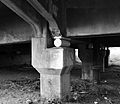
Pinned support

A pinned support attaches the only web of a beam to a girder called a shear connection. The support can exert a force on a member acting in any direction and prevent translational movements, or relative displacement of the member-ends in all directions but cannot prevent any rotational movements. [1] Its reaction forces are single linear forces of unknown direction or horizontal and vertical forces which are components of the single force of unknown direction. [5]

A pinned support is just like a human elbow. It can be extended and flexed (rotation), but you cannot move your forearm left to right (translation). One benefit of pinned supports is not having internal moment forces and only their axial force playing a big role in designing them. However, a single pinned support cannot completely restrain a structure. At least two supports are needed to resist the moment. [7] Applying in trusses is one frequent way we can use this support.
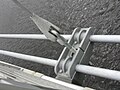
Fixed support

Rigid or fixed supports maintain the angular relationship between the joined elements and provide both force and moment resistance. It exerts forces acting in any direction and prevents all translational movements (horizontal and vertical) as well as all rotational movements of a member. These supports’ reaction forces are horizontal and vertical components of a linear resultant; a moment. [5] It is a rigid type of support or connection. The application of the fixed support is beneficial when we can only use single support, and people most widely used this type as the only support for a cantilever. [7] They are common in beam-to-column connections of moment-resisting steel frames and beam, column and slab connections in concrete frames.
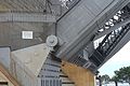
Hanger support

A hanger support only exerts a force and prevents a member from acting or translating away in the direction of the hanger. However, this support cannot prevent translational movement in all directions and any rotational movement. [1] [5] This is one of the simplest structural forms in which the elements are in pure tension. Structures of this type range from simple guyed or stayed structures to large cable-supported bridge and roof systems. [4]

Simple support

A simple support is basically where the structural member rests on an external structure as in two concrete blocks holding a resting plank of wood on their tops. This support is similar to roller support in a sense that restrains vertical forces but not horizontal forces. Therefore, it is not widely used in real life structures unless the engineer can be sure that the member will not translate. [7]

Varieties of support

Varieties of support [8]
NameSchematic diagramSimple figureAllowed movementReaction
VerticalHorizontalRotation (Moment)DirectionNumber
Roller or simple (movable) support
Movable support (real).svg
Movable support 1.svg
NoYesYes
Movable support reaction.svg
1
Movable support 2.svg
Pinned or hinged support
Hinged support (real).svg
Hinged support.svg
NoNoYes
Hinged support reaction.svg
2
Middle hinge (for axial member)
Middle hinge axial (real).svg
Middle hinge.svg
NoNoYes2
Fixed support
Fixed support (real).svg
Fixed support.svg
NoNoNo
Fixed support reaction.svg
3
Middle hinge (for beam member)
Middle hinge beam (real).svg
NoYesNo2

See also

Related Research Articles

<span class="mw-page-title-main">Structural engineering</span> Sub-discipline of civil engineering dealing with the creation of man made structures

Structural engineering is a sub-discipline of civil engineering in which structural engineers are trained to design the 'bones and muscles' that create the form and shape of human-made structures. Structural engineers also must understand and calculate the stability, strength, rigidity and earthquake-susceptibility of built structures for buildings and nonbuilding structures. The structural designs are integrated with those of other designers such as architects and building services engineer and often supervise the construction of projects by contractors on site. They can also be involved in the design of machinery, medical equipment, and vehicles where structural integrity affects functioning and safety. See glossary of structural engineering.

Structural analysis is a branch of solid mechanics which uses simplified models for solids like bars, beams and shells for engineering decision making. Its main objective is to determine the effect of loads on the physical structures and their components. In contrast to theory of elasticity, the models used in structure analysis are often differential equations in one spatial variable. Structures subject to this type of analysis include all that must withstand loads, such as buildings, bridges, aircraft and ships. Structural analysis uses ideas from applied mechanics, materials science and applied mathematics to compute a structure's deformations, internal forces, stresses, support reactions, velocity, accelerations, and stability. The results of the analysis are used to verify a structure's fitness for use, often precluding physical tests. Structural analysis is thus a key part of the engineering design of structures.

<span class="mw-page-title-main">Truss</span> Rigid structure that consists of two-force members only

A truss is an assembly of members such as beams, connected by nodes, that creates a rigid structure.

<span class="mw-page-title-main">Space frame</span> Rigid three dimensional load bearing truss structure

In architecture and structural engineering, a space frame or space structure is a rigid, lightweight, truss-like structure constructed from interlocking struts in a geometric pattern. Space frames can be used to span large areas with few interior supports. Like the truss, a space frame is strong because of the inherent rigidity of the triangle; flexing loads are transmitted as tension and compression loads along the length of each strut.

<span class="mw-page-title-main">Beam (structure)</span> Structural element capable of withstanding loads by resisting bending

A beam is a structural element that primarily resists loads applied laterally to the beam's axis. Its mode of deflection is primarily by bending. The loads applied to the beam result in reaction forces at the beam's support points. The total effect of all the forces acting on the beam is to produce shear forces and bending moments within the beams, that in turn induce internal stresses, strains and deflections of the beam. Beams are characterized by their manner of support, profile, equilibrium conditions, length, and their material.

<span class="mw-page-title-main">Seismic retrofit</span> Modification of existing structures to make them more resistant to seismic activity

Seismic retrofitting is the modification of existing structures to make them more resistant to seismic activity, ground motion, or soil failure due to earthquakes. With better understanding of seismic demand on structures and with our recent experiences with large earthquakes near urban centers, the need of seismic retrofitting is well acknowledged. Prior to the introduction of modern seismic codes in the late 1960s for developed countries and late 1970s for many other parts of the world, many structures were designed without adequate detailing and reinforcement for seismic protection. In view of the imminent problem, various research work has been carried out. State-of-the-art technical guidelines for seismic assessment, retrofit and rehabilitation have been published around the world – such as the ASCE-SEI 41 and the New Zealand Society for Earthquake Engineering (NZSEE)'s guidelines. These codes must be regularly updated; the 1994 Northridge earthquake brought to light the brittleness of welded steel frames, for example.

A tie, strap, tie rod, eyebar, guy-wire, suspension cables, or wire ropes, are examples of linear structural components designed to resist tension. It is the opposite of a strut or column, which is designed to resist compression. Ties may be made of any tension resisting material.

<span class="mw-page-title-main">Jackscrew</span> Mechanical lifting device operated by turning a leadscrew

A jackscrew, or screw jack, is a type of jack that is operated by turning a leadscrew. It is commonly used to lift moderately and heavy weights, such as vehicles; to raise and lower the horizontal stabilizers of aircraft; and as adjustable supports for heavy loads, such as the foundations of houses.

<span class="mw-page-title-main">Portal frame</span>

Portal frame is a construction technique where vertical supports are connected to horizontal beams or trusses via fixed joints with designed-in moment-resisting capacity. The result is wide spans and open floors.

<span class="mw-page-title-main">Tied-arch bridge</span>

A tied-arch bridge is an arch bridge in which the outward horizontal forces of the arch(es) caused by tension at the arch ends to a foundation are countered by equal tension of its own gravity plus any element of the total deck structure such great arch(es) support. The arch(es) have strengthened chord(s) that run to a strong part of the deck structure or to independent tie-rods below the arch ends.

<span class="mw-page-title-main">Steel building</span>

A steel building is a metal structure fabricated with steel for the internal support and for exterior cladding, as opposed to steel framed buildings which generally use other materials for floors, walls, and external envelope. Steel buildings are used for a variety of purposes including storage, work spaces and living accommodation. They are classified into specific types depending on how they are used.

In structural engineering, a diaphragm is a structural element that transmits lateral loads to the vertical resisting elements of a structure. Diaphragms are typically horizontal but can be sloped in a gable roof on a wood structure or concrete ramp in a parking garage. The diaphragm forces tend to be transferred to the vertical resisting elements primarily through in-plane shear stress. The most common lateral loads to be resisted are those resulting from wind and earthquake actions, but other lateral loads such as lateral earth pressure or hydrostatic pressure can also be resisted by diaphragm action.

<span class="mw-page-title-main">Direct integration of a beam</span>

Direct integration is a structural analysis method for measuring internal shear, internal moment, rotation, and deflection of a beam.

<span class="mw-page-title-main">Structural engineering theory</span>

Structural engineering depends upon a detailed knowledge of loads, physics and materials to understand and predict how structures support and resist self-weight and imposed loads. To apply the knowledge successfully structural engineers will need a detailed knowledge of mathematics and of relevant empirical and theoretical design codes. They will also need to know about the corrosion resistance of the materials and structures, especially when those structures are exposed to the external environment.

<span class="mw-page-title-main">Yaw system</span>

The yaw system of wind turbines is the component responsible for the orientation of the wind turbine rotor towards the wind.

A pipe support or pipe hanger is a designed element that transfer the load from a pipe to the supporting structures. The load includes the weight of the pipe proper, the content that the pipe carries, all the pipe fittings attached to pipe, and the pipe covering such as insulation. The four main functions of a pipe support are to anchor, guide, absorb shock, and support a specified load. Pipe supports used in high or low temperature applications may contain insulation materials. The overall design configuration of a pipe support assembly is dependent on the loading and operating conditions.

A buckling-restrained brace (BRB) is a structural brace in a building, designed to allow the building to withstand cyclical lateral loadings, typically earthquake-induced loading. It consists of a slender steel core, a concrete casing designed to continuously support the core and prevent buckling under axial compression, and an interface region that prevents undesired interactions between the two. Braced frames that use BRBs – known as buckling-restrained braced frames, or BRBFs – have significant advantages over typical braced frames.

<span class="mw-page-title-main">Bridge bearing</span>

A bridge bearing is a component of a bridge which typically provides a resting surface between bridge piers and the bridge deck. The purpose of a bearing is to allow controlled movement and thereby reduce the stresses involved. Possible causes of movement are thermal expansion and contraction, creep, shrinkage, or fatigue due to the properties of the material used for the bearing. External sources of movement include the settlement of the ground below, thermal expansion, and seismic activity. There are several different types of bridge bearings which are used depending on a number of different factors including the bridge span, loading conditions, and performance specifications. The oldest form of bridge bearing is simply two plates resting on top of each other. A common form of modern bridge bearing is the elastomeric bridge bearing. Another type of bridge bearing is the mechanical bridge bearing. There are several types of mechanical bridge bearing, such as the pinned bearing, which in turn includes specific types such as the rocker bearing, and the roller bearing. Another type of mechanical bearing is the fixed bearing, which allows rotation, but not other forms of movement.

<span class="mw-page-title-main">Infill wall</span>

The infill wall is the supported wall that closes the perimeter of a building constructed with a three-dimensional framework structure. Therefore, the structural frame ensures the bearing function, whereas the infill wall serves to separate inner and outer space, filling up the boxes of the outer frames. The infill wall has the unique static function to bear its own weight. The infill wall is an external vertical opaque type of closure. With respect to other categories of wall, the infill wall differs from the partition that serves to separate two interior spaces, yet also non-load bearing, and from the load bearing wall. The latter performs the same functions of the infill wall, hygro-thermically and acoustically, but performs static functions too.

<span class="mw-page-title-main">Earthquake rotational loading</span>

Earthquake rotational loading indicates the excitation of structures due to the torsional and rocking components of seismic actions. Nathan M. Newmark was the first researcher who showed that this type of loading may result in unexpected failure of structures, and its influence should be considered in design codes. There are various phenomena that may lead to the earthquake rotational loading of structures, such as propagation of body wave, surface wave, special rotational wave, block rotation, topographic effect, and soil structure interaction.

References

  1. 1 2 3 4 5 Ashwani Bedi and Ramsey Dabby (2012). Structure for Architects: A Primer. Canada: John Wileys and Sons.
  2. Ching, Francis D.K; Onouye, Barry; Zuberbuhler, Douglas (2009). Building Structures Illustrated: Patterns, Systems and Design . Hoboken, New Jersey: John Wiley & Sons.
  3. 1 2 Schueller, Wolfgang (25 August 2015). "Building Structures as Architecture". SlideShare. LinkedIn Corporation. Retrieved 18 September 2018.
  4. 1 2 West, Harry H. (1993). Fundamentals of Structural Analysis. John Wilsey & Sons, Inc.
  5. 1 2 3 4 5 "Statics of Structural Supports" (PDF). University of Kentucky College of Engineering. Retrieved 16 October 2018.
  6. Chris H. Luebkeman and Donald Peting (1998). "Support and Connection Types". MIT (Massachusetts Institute of Technology). Google Custom Search. Retrieved 18 September 2018.
  7. 1 2 3 "Support types-notes member (civil, architectural structure)". SlideShare. LinkedIn Corporation. 2 February 2017. Retrieved 22 October 2018.
  8. Tatsurō Sakimoto (1991). Kōzō rikigaku. 001[Structural Dynamics 001]. Kiso doboku kōgaku shirīzu (in Japanese). Morikitashuppan. pp. 36–40. ISBN   4-627-42510-4.