Structural element capable of withstanding loads by resisting bending
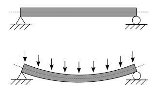
A statically determinate beam, bending (sagging) under a uniformly distributed load, which includes its own weight
A beam is a structural element that primarily resists loads applied laterally across its axis (an element designed to carry a load pushing parallel to its axis would be a strut or column). A beam's mode of deflection is primarily by bending, as loads produce reaction forces at the beam's support points and internal bending moments, shear, stresses, strains, and deflections. Beams are characterized by their manner of support, profile (shape of cross-section), equilibrium conditions, length, and material.
Beams are traditionally descriptions of building or civil engineering structural elements, where the beams are horizontal and carry vertical loads. However, any structure may contain beams, such as automobile frames, aircraft components, machine frames, and other mechanical or structural systems. Any structural element, in any orientation, that primarily resists loads applied laterally across the element's axis is a beam.
In the beam equation, the variable I represents the second moment of area or moment of inertia: it is the sum, along the axis, of dA·r2, where r is the distance from the neutral axis and dA is a small patch of area. It measures not only the total area of the beam section, but the square of each patch's distance from the axis. A larger value of I indicates a stiffer beam, more resistant to bending.
Stress
Diagram of stiffness of a simple square beam (A) and universal beam (B). The universal beam flange sections are three times further apart than the solid beam's upper and lower halves. The second moment of inertia of the universal beam is nine times that of the square beam of equal cross section (universal beam web ignored for simplification)
Loads on a beam induce internal compressive, tensile and shear stresses (assuming no torsion or axial loading). Typically, under gravity loads, the beam bends into a slightly circular arc, with its original length compressed at the top to form an arc of smaller radius, while correspondingly stretched at the bottom to enclose an arc of larger radius in tension. This is known as sagging; while a configuration with the top in tension, for example over a support, is known as hogging. The axis of the beam retaining its original length, generally halfway between the top and bottom, is under neither compression nor tension, and defines the neutral axis (dotted line in the beam figure).
Above the supports, the beam is exposed to shear stress. There are some reinforced concrete beams in which the concrete is entirely in compression with tensile forces taken by steel tendons. These beams are known as prestressed concrete beams, and are fabricated to produce a compression more than the expected tension under loading conditions. High strength steel tendons are stretched while the beam is cast over them. Then, when the concrete has cured, the tendons are slowly released and the beam is immediately under eccentric axial loads. This eccentric loading creates an internal moment, and, in turn, increases the moment-carrying capacity of the beam. Prestressed beams are commonly used on highway bridges.
The primary tool for structural analysis of beams is the Euler–Bernoulli beam equation. This equation accurately describes the elastic behaviour of slender beams where the cross sectional dimensions are small compared to the length of the beam. For beams that are not slender a different theory needs to be adopted to account for the deformation due to shear forces and, in dynamic cases, the rotary inertia. The beam formulation adopted here is that of Timoshenko and comparative examples can be found in NAFEMS Benchmark Challenge Number 7.[4] Other mathematical methods for determining the deflection of beams include "method of virtual work" and the "slope deflection method". Engineers are interested in determining deflections because the beam may be in direct contact with a brittle material such as glass. Beam deflections are also minimized for aesthetic reasons. A visibly sagging beam, even if structurally safe, is unsightly and to be avoided. A stiffer beam (high modulus of elasticity and/or one of higher second moment of area) creates less deflection.
Most beams in reinforced concrete buildings have rectangular cross sections, but a more efficient cross section for a beam is an Ɪ- or H-shaped section which is typically seen in steel construction. Because of the parallel axis theorem and the fact that most of the material is away from the neutral axis, the second moment of area of the beam increases, which in turn increases the stiffness.
An Ɪ beam is only the most efficient shape in one direction of bending: up and down looking at the profile as an 'Ɪ'. If the beam is bent side to side, it functions as an 'H', where it is less efficient. The most efficient shape for both directions in 2D is a box (a square shell); the most efficient shape for bending in any direction, however, is a cylindrical shell or tube. For unidirectional bending, the Ɪ-beam or wide flange beam is superior.[5]
Efficiency means that for the same cross sectional area (volume of beam per length) subjected to the same loading conditions, the beam deflects less.
Other shapes, like L-beam (angles), C (channels), T-beam and double-T or tubes, are also used in construction when there are special requirements.
A haunched beam is one with a curved bottom edge, so the beam is deeper at the ends, and less deep in the middle. It is not an arch, because the top of a haunched beam is flat and straight. A haunched beam usually has a graceful appearance, and weighs less than beams with a flat bottom. Haunched beams are often more costly than normal beams, because they typically must be custom-built for the site, and cannot take advantage of the benefits of mass production.
Walers and struts
This section needs expansionwith: a broader description of walers and their applications, as well as struts. You can help by adding to it. (September 2025)
This system provides horizontal bracing for small trenches, ensuring the secure installation of utilities. It's specifically designed to work in conjunction with steel trench sheets.[6]
A thin walled beam is a very useful type of beam (structure). The cross section of thin walled beams is made up from thin panels connected among themselves to create closed or open cross sections of a beam (structure). Typical closed sections include round, square, and rectangular tubes. Open sections include I-beams, T-beams, L-beams, and so on. Thin walled beams exist because their bending stiffness per unit cross sectional area is much higher than that for solid cross sections such a rod or bar. In this way, stiff beams can be achieved with minimum weight. Thin walled beams are particularly useful when the material is a composite laminate. Pioneer work on composite laminate thin walled beams was done by Librescu.
The torsional stiffness of a beam is greatly influenced by its cross sectional shape. For open sections, such as I sections, warping deflections occur which, if restrained, greatly increase the torsional stiffness.[7]
↑ "Beam" def. 1. Whitney, William Dwight, and Benjamin E. Smith. The Century dictionary and cyclopedia. vol, 1. New York: Century Co., 1901. 487. Print.
↑ Ching, Frank. A visual dictionary of architecture. New York: Van Nostrand Reinhold, 1995. 8–9. Print.
This page is based on this Wikipedia article Text is available under the CC BY-SA 4.0 license; additional terms may apply. Images, videos and audio are available under their respective licenses.