I-beam

Last updated

An I-beam used to support the first floor of a house I-Beam 002.JPG
An I-beam used to support the first floor of a house

An I-beam is any of various structural members with an I or H-shaped cross-section. Technical terms for similar items include H-beam (for universal column, UC), w-beam (for "wide flange"), universal beam (UB), rolled steel joist (RSJ), or double-T (especially in Polish, Bulgarian, Spanish, Italian and German). I-beams are typically made of structural steel and serve a wide variety of construction uses.

Contents

The horizontal elements of the I are called flanges, and the vertical element is known as the "web". The web resists shear forces, while the flanges resist most of the bending moment experienced by the beam. The Euler–Bernoulli beam equation shows that the I-shaped section is a very efficient form for carrying both bending and shear loads in the plane of the web. On the other hand, the cross-section has a reduced capacity in the transverse direction, and is also inefficient in carrying torsion, for which hollow structural sections are often preferred.

History

Mark di Suvero's Victor's Lament (foreground in red) on the campus of Muhlenberg College in Allentown, Pennsylvania, is an I-beam sculpture paying tribute to the rich history of steelmaking in the Lehigh Valley region of the eastern Pennsylvania. Muhlenberg College.jpg
Mark di Suvero's Victor's Lament (foreground in red) on the campus of Muhlenberg College in Allentown, Pennsylvania, is an I-beam sculpture paying tribute to the rich history of steelmaking in the Lehigh Valley region of the eastern Pennsylvania.

In 1849, the method of producing an I-beam, as rolled from a single piece of wrought iron, [1] was patented by Alphonse Halbou of Forges de la Providence in Marchienne-au-Pont, Belgium. [2]

Bethlehem Steel, headquartered in Bethlehem, Pennsylvania, was a leading supplier of rolled structural steel of various cross-sections in American bridge and skyscraper work of the mid-20th century. [3] Rolled cross-sections now have been partially displaced in such work by fabricated cross-sections.

Overview

A typical cross-section of I-beams Ibeam.svg
A typical cross-section of I-beams

There are two standard I-beam forms:

I-beams are commonly made of structural steel but may also be formed from aluminium or other materials. A common type of I-beam is the rolled steel joist (RSJ), sometimes incorrectly rendered as reinforced steel joist. British and European standards also specify Universal Beams (UBs) and Universal Columns (UCs). These sections have parallel flanges, shown as "W-Section" in the accompanying illustration, as opposed to the varying thickness of RSJ flanges, illustrated as "S-Section", which are seldom now rolled in the United Kingdom. Parallel flanges are easier to connect to and do away with the need for tapering washers. UCs have equal or near-equal width and depth and are more suited to being oriented vertically to carry axial load such as columns in multi-storey construction, while UBs are significantly deeper than they are wide are more suited to carrying bending load such as beam elements in floors.

I-joists, I-beams engineered from wood with fiberboard or laminated veneer lumber, or both, are also becoming increasingly popular in construction, especially residential, as they are both lighter and less prone to warping than solid wooden joists. However, there has been some concern as to their rapid loss of strength in a fire if unprotected.

Design

An I-beam vibrating in torsion mode Beam mode 2.gif
An I-beam vibrating in torsion mode

I-beams are widely used in the construction industry and are available in a variety of standard sizes. Tables are available to allow easy selection of a suitable steel I-beam size for a given applied load. I-beams may be used both as beams and as columns.

I-beams may be used both on their own, or acting compositely with another material, typically concrete. Design may be governed by any of the following criteria:

Design for bending

Poutre flexion deviee.svg A beam under bending sees high stresses along the axial fibers that are farthest from the neutral axis. To prevent failure, most of the material in the beam must be located in these regions. Comparatively little material is needed in the area close to the neutral axis. This observation is the basis of the I-beam cross-section; the neutral axis runs along the center of the web which can be relatively thin and most of the material can be concentrated in the flanges.

The ideal beam is the one with the least cross-sectional area (and hence requiring the least material) needed to achieve a given section modulus. Since the section modulus depends on the value of the moment of inertia, an efficient beam must have most of its material located as far from the neutral axis as possible. The farther a given amount of material is from the neutral axis, the larger is the section modulus and hence a larger bending moment can be resisted.

When designing a symmetric I-beam to resist stresses due to bending the usual starting point is the required section modulus. If the allowable stress is σmax and the maximum expected bending moment is Mmax, then the required section modulus is given by [4]

where I is the moment of inertia of the beam cross-section and c is the distance of the top of the beam from the neutral axis (see beam theory for more details).

For a beam of cross-sectional area a and height h, the ideal cross-section would have half the area at a distance h/2 above the cross-section and the other half at a distance h/2 below the cross-section. [4] For this cross-section

However, these ideal conditions can never be achieved because material is needed in the web for physical reasons, including to resist buckling. For wide-flange beams, the section modulus is approximately

which is superior to that achieved by rectangular beams and circular beams.

Issues

Though I-beams are excellent for unidirectional bending in a plane parallel to the web, they do not perform as well in bidirectional bending. These beams also show little resistance to twisting and undergo sectional warping under torsional loading. For torsion dominated problems, box beams and other types of stiff sections are used in preference to the I-beam.

Shapes and materials in the United States

A rusty riveted steel I-beam Rostiger Stahltraeger.jpg
A rusty riveted steel I-beam

In the United States, the most commonly mentioned I-beam is the wide-flange (W) shape. These beams have flanges whose inside surfaces are parallel over most of their area. Other I-beams include American Standard (designated S) shapes, in which inner flange surfaces are not parallel, and H-piles (designated HP), which are typically used as pile foundations. Wide-flange shapes are available in grade ASTM A992, [5] which has generally replaced the older ASTM grades A572 and A36. Ranges of yield strength:

Like most steel products, I-beams often contain some recycled content.

Standards

The following standards define the shape and tolerances of I-beam steel sections:

European standards

AISC manual

The American Institute of Steel Construction (AISC) publishes the Steel Construction Manual for designing structures of various shapes. It documents the common approaches, Allowable Strength Design (ASD) and Load and Resistance Factor Design (LRFD), (starting with 13th ed.) to create such designs.

Other

Designation and terminology

The dimension of a wide-flange I-beam I-BeamCrossSection.svg
The dimension of a wide-flange I-beam

In the United States, steel I-beams are commonly specified using the depth and weight of the beam. For example, a "W10x22" beam is approximately 10 in (254 mm) in depth with a nominal height of the I-beam from the outer face of one flange to the outer face of the other flange, and weighs 22 lb/ft (33 kg/m). Wide flange section beams often vary from their nominal depth. In the case of the W14 series, they may be as deep as 22.84 in (580 mm). [7] '

In Canada, steel I-beams are now commonly specified using the depth and weight of the beam in metric terms. For example, a "W250x33" beam is approximately 250 millimetres (9.8 in) in depth (height of the I-beam from the outer face of one flange to the outer face of the other flange) and weighs approximately 33 kg/m (22 lb/ft; 67 lb/yd). [8] I-beams are still available in US sizes from many Canadian manufacturers.

In Mexico, steel I-beams are called IR and commonly specified using the depth and weight of the beam in metric terms. For example, a "IR250x33" beam is approximately 250 mm (9.8 in) in depth (height of the I-beam from the outer face of one flange to the outer face of the other flange) and weighs approximately 33 kg/m (22 lb/ft). [9]

In India, I-beams are designated as ISMB, ISJB, ISLB, ISWB. ISMB: Indian Standard Medium Weight Beam, ISJB: Indian Standard Junior Beams, ISLB: Indian Standard Light Weight Beams, and ISWB: Indian Standard Wide Flange Beams. Beams are designated as per respective abbreviated reference followed by the depth of section, such as for example ISMB 450, where 450 is the depth of section in millimetres (mm). The dimensions of these beams are classified as per IS:808 (as per BIS).[ citation needed ]

In the United Kingdom, these steel sections are commonly specified with a code consisting of the major dimension, usually the depth, -x-the minor dimension-x-the mass per metre-ending with the section type, all measurements being metric. Therefore, a 152x152x23UC would be a column section (UC = universal column) of approximately 152 mm (6.0 in) depth, 152 mm width and weighing 23 kg/m (46 lb/yd) of length. [10]

In Australia, these steel sections are commonly referred to as Universal Beams (UB) or Columns (UC). The designation for each is given as the approximate height of the beam, the type (beam or column) and then the unit metre rate (e.g., a 460UB67.1 is an approximately 460 mm (18.1 in) deep universal beam that weighs 67.1 kg/m (135 lb/yd)). [6]

Cellular beams

Cellular beams are the modern version of the traditional castellated beam, which results in a beam approximately 40–60% deeper than its parent section. The exact finished depth, cell diameter and cell spacing are flexible. A cellular beam is up to 1.5 times stronger than its parent section and is therefore utilized to create efficient large span constructions. [11]

See also

Related Research Articles

<span class="mw-page-title-main">Column</span> Structural element that transmits weight from above to below

A column or pillar in architecture and structural engineering is a structural element that transmits, through compression, the weight of the structure above to other structural elements below. In other words, a column is a compression member. The term column applies especially to a large round support with a capital and a base or pedestal, which is made of stone, or appearing to be so. A small wooden or metal support is typically called a post. Supports with a rectangular or other non-round section are usually called piers.

<span class="mw-page-title-main">Truss</span> Rigid structure that consists of two-force members only

A truss is an assembly of members such as beams, connected by nodes, that creates a rigid structure.

<span class="mw-page-title-main">Beam (structure)</span> Structural element capable of withstanding loads by resisting bending

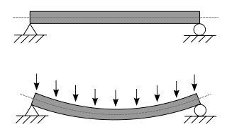
A beam is a structural element that primarily resists loads applied laterally across the beam's axis. Its mode of deflection is primarily by bending, as loads produce reaction forces at the beam's support points and internal bending moments, shear, stresses, strains, and deflections. Beams are characterized by their manner of support, profile, equilibrium conditions, length, and material.

<span class="mw-page-title-main">Buckling</span> Sudden change in shape of a structural component under load

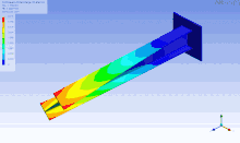
In structural engineering, buckling is the sudden change in shape (deformation) of a structural component under load, such as the bowing of a column under compression or the wrinkling of a plate under shear. If a structure is subjected to a gradually increasing load, when the load reaches a critical level, a member may suddenly change shape and the structure and component is said to have buckled. Euler's critical load and Johnson's parabolic formula are used to determine the buckling stress of a column.

<span class="mw-page-title-main">Hollow structural section</span> Type of metal profile

A hollow structural section (HSS) is a type of metal profile with a hollow cross section. The term is used predominantly in the United States, or other countries which follow US construction or engineering terminology.

<span class="mw-page-title-main">Plate girder bridge</span> Type of bridge

A plate girder bridge is a bridge supported by two or more plate girders.

<span class="mw-page-title-main">Steel frame</span> Building technique using skeleton frames of vertical steel columns

Steel frame is a building technique with a "skeleton frame" of vertical steel columns and horizontal I-beams, constructed in a rectangular grid to support the floors, roof and walls of a building which are all attached to the frame. The development of this technique made the construction of the skyscraper possible.

<span class="mw-page-title-main">Girder</span> Support beam used in construction

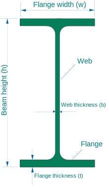
A girder is a beam used in construction. It is the main horizontal support of a structure which supports smaller beams. Girders often have an I-beam cross section composed of two load-bearing flanges separated by a stabilizing web, but may also have a box shape, Z shape, or other forms. Girders are commonly used to build bridges.

Specific modulus is a materials property consisting of the elastic modulus per mass density of a material. It is also known as the stiffness to weight ratio or specific stiffness. High specific modulus materials find wide application in aerospace applications where minimum structural weight is required. The dimensional analysis yields units of distance squared per time squared. The equation can be written as:

<span class="mw-page-title-main">Structural steel</span> Type of steel used in construction

Structural steel is a category of steel used for making construction materials in a variety of shapes. Many structural steel shapes take the form of an elongated beam having a profile of a specific cross section. Structural steel shapes, sizes, chemical composition, mechanical properties such as strengths, storage practices, etc., are regulated by standards in most industrialized countries.

<span class="mw-page-title-main">Girder bridge</span> Bridge built of girders placed on bridge abutments and foundation piers

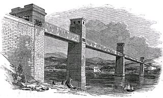
A girder bridge is a bridge that uses girders as the means of supporting its deck. The two most common types of modern steel girder bridges are plate and box.

<span class="mw-page-title-main">Box girder</span> Type of girder

A box girder or tubular girder is a girder that forms an enclosed tube with multiple walls, as opposed to an I- or H-beam. Originally constructed of wrought iron joined by riveting, they are now made of rolled or welded steel, aluminium extrusions or prestressed concrete.
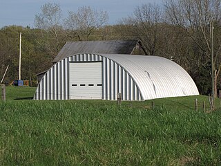
Steel Design, or more specifically, Structural Steel Design, is an area of structural engineering used to design steel structures. These structures include schools, houses, bridges, commercial centers, tall buildings, warehouses, aircraft, ships and stadiums. The design and use of steel frames are commonly employed in the design of steel structures. More advanced structures include steel plates and shells.

Section modulus is a geometric property for a given cross-section used in the design of beams or flexural members. Other geometric properties used in design include area for tension and shear, radius of gyration for compression, and second moment of area and polar second moment of area for stiffness. Any relationship between these properties is highly dependent on the shape in question. Equations for the section moduli of common shapes are given below. There are two types of section moduli, the elastic section modulus and the plastic section modulus. The section moduli of different profiles can also be found as numerical values for common profiles in tables listing properties of such.

<span class="mw-page-title-main">Cold-formed steel</span> Steel products shaped by cold-working processes

Cold-formed steel (CFS) is the common term for steel products shaped by cold-working processes carried out near room temperature, such as rolling, pressing, stamping, bending, etc. Stock bars and sheets of cold-rolled steel (CRS) are commonly used in all areas of manufacturing. The terms are opposed to hot-formed steel and hot-rolled steel.

Process duct work conveys large volumes of hot, dusty air from processing equipment to mills, baghouses to other process equipment. Process duct work may be round or rectangular. Although round duct work costs more to fabricate than rectangular duct work, it requires fewer stiffeners and is favored in many applications over rectangular ductwork.

<span class="mw-page-title-main">Structural engineering theory</span>

Structural engineering depends upon a detailed knowledge of loads, physics and materials to understand and predict how structures support and resist self-weight and imposed loads. To apply the knowledge successfully structural engineers will need a detailed knowledge of mathematics and of relevant empirical and theoretical design codes. They will also need to know about the corrosion resistance of the materials and structures, especially when those structures are exposed to the external environment.

ASTM A992 steel is a structural steel alloy often used in the US for steel wide-flange and I beams. Like other carbon steels, the density of ASTM A992 steel is approximately 7850 kg/m3. ASTM A992 steel has the following minimum mechanical properties, according to ASTM specification A992/A992M. Tensile yield strength, 345 MPa (50 ksi); tensile ultimate strength, 450 MPa (65 ksi); strain to rupture in a 200-mm-long test specimen, 18%; strain to rupture in a 50-mm-long test specimen, 21%.

The structural channel, also known as a C-channel or Parallel Flange Channel (PFC), is a type of beam, used primarily in building construction and civil engineering. Its cross section consists of a wide "web", usually but not always oriented vertically, and two "flanges" at the top and bottom of the web, only sticking out on one side of the web. It is distinguished from I-beam or H-beam or W-beam type steel cross sections in that those have flanges on both sides of the web.

This glossary of structural engineering terms pertains specifically to structural engineering and its sub-disciplines. Please see glossary of engineering for a broad overview of the major concepts of engineering.

References

  1. Forsyth, M. Structures and Construction in Historic Building Conservation. p. 179.
  2. Thomas Derdak, Jay P. Pederson (1999). International directory of company histories. Vol. 26. St. James Press. p. 82. ISBN   978-1-55862-385-9.
  3. "Forging America: The History of Bethlehem Steel". Morning Call Supplement. The Morning Call. 14 December 2003. Archived from the original on 27 April 2011. Retrieved 24 September 2010.
  4. 1 2 Gere and Timoshenko, 1997, Mechanics of Materials, PWS Publishing Company.
  5. ASTM A992?A992M Standard Specification for Structural Steel Shapes. American Society for Testing and Materials. 2006. doi:10.1520/A0992_A0992M-06A.
  6. 1 2 Hot rolled and structural steel products – Fifth edition Archived 10 April 2013 at the Wayback Machine Onesteel. Retrieved 18 December 2015.
  7. AISC Manual of Steel Construction 14th Edition
  8. Handbook of Steel Construction (9th ed.). Canadian Institute of Steel Construction. 2006. ISBN   978-0-88811-124-1.
  9. IMCA Manual of Steel Construction, 5th Edition.
  10. "Structural sections" (PDF). Corus Construction & Industrial. Archived from the original (PDF) on 15 February 2010.
  11. "Cellular Beams - Kloeckner Metals UK". kloecknermetalsuk.com. Retrieved 13 May 2017.

Further reading