Span (engineering)

Last updated

In engineering, span is the distance between two adjacent structural supports (e.g., two piers) of a structural member (e.g., a beam). Span is measured in the horizontal direction either between the faces of the supports (clear span) or between the centers of the bearing surfaces (effective span): [1]

Contents

Span definitions.png

A span can be closed by a solid beam or by a rope. The first kind is used for bridges, the second one for power lines, overhead telecommunication lines, some type of antennas or for aerial tramways.[ citation needed ]

Side view of a simply supported beam (top) bending under an evenly distributed load (bottom). Bending.svg
Side view of a simply supported beam (top) bending under an evenly distributed load (bottom).

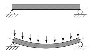
Span is a significant factor in finding the strength and size of a beam as it determines the maximum bending moment and deflection. The maximum bending moment and deflection in the pictured beam is found using: [2]

where

= Uniformly distributed load
= Length of the beam between two supports (span)
= Modulus of elasticity
= Area moment of inertia

The maximum bending moment and deflection occur midway between the two supports. From this it follows that if the span is doubled, the maximum moment (and with it the stress) will quadruple, and deflection will increase by a factor of sixteen.

See also

Related Research Articles

<span class="mw-page-title-main">Cantilever</span> Beam anchored at only one end

A cantilever is a rigid structural element that extends horizontally and is unsupported at one end. Typically it extends from a flat vertical surface such as a wall, to which it must be firmly attached. Like other structural elements, a cantilever can be formed as a beam, plate, truss, or slab.

<span class="mw-page-title-main">Buckling</span> Sudden change in shape of a structural component under load

In structural engineering, buckling is the sudden change in shape (deformation) of a structural component under load, such as the bowing of a column under compression or the wrinkling of a plate under shear. If a structure is subjected to a gradually increasing load, when the load reaches a critical level, a member may suddenly change shape and the structure and component is said to have buckled. Euler's critical load and Johnson's parabolic formula are used to determine the buckling stress of a column.

<span class="mw-page-title-main">Bending</span> Strain caused by an external load

In applied mechanics, bending characterizes the behavior of a slender structural element subjected to an external load applied perpendicularly to a longitudinal axis of the element.

<span class="mw-page-title-main">Euler–Bernoulli beam theory</span> Method for load calculation in construction

Euler–Bernoulli beam theory is a simplification of the linear theory of elasticity which provides a means of calculating the load-carrying and deflection characteristics of beams. It covers the case corresponding to small deflections of a beam that is subjected to lateral loads only. By ignoring the effects of shear deformation and rotatory inertia, it is thus a special case of Timoshenko–Ehrenfest beam theory. It was first enunciated circa 1750, but was not applied on a large scale until the development of the Eiffel Tower and the Ferris wheel in the late 19th century. Following these successful demonstrations, it quickly became a cornerstone of engineering and an enabler of the Second Industrial Revolution.

<span class="mw-page-title-main">I-beam</span> Construction element

An I-beam is any of various structural members with an I or H-shaped cross-section. Technical terms for similar items include H-beam, w-beam, universal beam (UB), rolled steel joist (RSJ), or double-T. I-beams are typically made of structural steel and serve a wide variety of construction uses.

<span class="mw-page-title-main">Delamination</span> Mode of failure for which a material fractures into layers

Delamination is a mode of failure where a material fractures into layers. A variety of materials, including laminate composites and concrete, can fail by delamination. Processing can create layers in materials, such as steel formed by rolling and plastics and metals from 3D printing which can fail from layer separation. Also, surface coatings, such as paints and films, can delaminate from the coated substrate.

<span class="mw-page-title-main">Flexural strength</span> Material property

Flexural strength, also known as modulus of rupture, or bend strength, or transverse rupture strength is a material property, defined as the stress in a material just before it yields in a flexure test. The transverse bending test is most frequently employed, in which a specimen having either a circular or rectangular cross-section is bent until fracture or yielding using a three-point flexural test technique. The flexural strength represents the highest stress experienced within the material at its moment of yield. It is measured in terms of stress, here given the symbol .

<span class="mw-page-title-main">Three-point flexural test</span> Standard procedure for measuring modulus of elasticity in bending

The three-point bending flexural test provides values for the modulus of elasticity in bending , flexural stress , flexural strain and the flexural stress–strain response of the material. This test is performed on a universal testing machine with a three-point or four-point bend fixture. The main advantage of a three-point flexural test is the ease of the specimen preparation and testing. However, this method has also some disadvantages: the results of the testing method are sensitive to specimen and loading geometry and strain rate.

<span class="mw-page-title-main">Bending moment</span> Force tending to bend a structural element

In solid mechanics, a bending moment is the reaction induced in a structural element when an external force or moment is applied to the element, causing the element to bend. The most common or simplest structural element subjected to bending moments is the beam. The diagram shows a beam which is simply supported at both ends; the ends can only react to the shear loads. Other beams can have both ends fixed ; therefore each end support has both bending moments and shear reaction loads. Beams can also have one end fixed and one end simply supported. The simplest type of beam is the cantilever, which is fixed at one end and is free at the other end. In reality, beam supports are usually neither absolutely fixed nor absolutely rotating freely.

<span class="mw-page-title-main">Neutral axis</span>

The neutral axis is an axis in the cross section of a beam or shaft along which there are no longitudinal stresses or strains.

Macaulay's method (the double integration method) is a technique used in structural analysis to determine the deflection of Euler-Bernoulli beams. Use of Macaulay's technique is very convenient for cases of discontinuous and/or discrete loading. Typically partial uniformly distributed loads (u.d.l.) and uniformly varying loads (u.v.l.) over the span and a number of concentrated loads are conveniently handled using this technique.

The moment distribution method is a structural analysis method for statically indeterminate beams and frames developed by Hardy Cross. It was published in 1930 in an ASCE journal. The method only accounts for flexural effects and ignores axial and shear effects. From the 1930s until computers began to be widely used in the design and analysis of structures, the moment distribution method was the most widely practiced method.

The slope deflection method is a structural analysis method for beams and frames introduced in 1914 by George A. Maney. The slope deflection method was widely used for more than a decade until the moment distribution method was developed. In the book, "The Theory and Practice of Modern Framed Structures", written by J.B Johnson, C.W. Bryan and F.E. Turneaure, it is stated that this method was first developed "by Professor Otto Mohr in Germany, and later developed independently by Professor G.A. Maney". According to this book, professor Otto Mohr introduced this method for the first time in his book, "Evaluation of Trusses with Rigid Node Connections" or "Die Berechnung der Fachwerke mit Starren Knotenverbindungen".

<span class="mw-page-title-main">Influence line</span>

In engineering, an influence line graphs the variation of a function at a specific point on a beam or truss caused by a unit load placed at any point along the structure. Common functions studied with influence lines include reactions, shear, moment, and deflection (Deformation). Influence lines are important in designing beams and trusses used in bridges, crane rails, conveyor belts, floor girders, and other structures where loads will move along their span. The influence lines show where a load will create the maximum effect for any of the functions studied.

<span class="mw-page-title-main">Shear and moment diagram</span> Structural design tool

Shear force and bending moment diagrams are analytical tools used in conjunction with structural analysis to help perform structural design by determining the value of shear forces and bending moments at a given point of a structural element such as a beam. These diagrams can be used to easily determine the type, size, and material of a member in a structure so that a given set of loads can be supported without structural failure. Another application of shear and moment diagrams is that the deflection of a beam can be easily determined using either the moment area method or the conjugate beam method.

<span class="mw-page-title-main">Deflection (engineering)</span> Degree to which part of a structural element is displaced under a given load

In structural engineering, deflection is the degree to which a part of a long structural element is deformed laterally under a load. It may be quantified in terms of an angle or a distance . A longitudinal deformation is called elongation.

<span class="mw-page-title-main">Structural engineering theory</span>

Structural engineering depends upon a detailed knowledge of loads, physics and materials to understand and predict how structures support and resist self-weight and imposed loads. To apply the knowledge successfully structural engineers will need a detailed knowledge of mathematics and of relevant empirical and theoretical design codes. They will also need to know about the corrosion resistance of the materials and structures, especially when those structures are exposed to the external environment.

In civil engineering and structural analysis Clapeyron's theorem of three moments is a relationship among the bending moments at three consecutive supports of a horizontal beam.

The four-point flexural test provides values for the modulus of elasticity in bending , flexural stress , flexural strain and the flexural stress-strain response of the material. This test is very similar to the three-point bending flexural test. The major difference being that with the addition of a fourth bearing the portion of the beam between the two loading points is put under maximum stress, as opposed to only the material right under the central bearing in the case of three-point bending.

<span class="mw-page-title-main">Euler's critical load</span> Formula to quantify column buckling under a given load

Euler's critical load or Euler's buckling load is the compressive load at which a slender column will suddenly bend or buckle. It is given by the formula:

References

  1. Brett 2012, p. 137.
  2. Gere, James M.; Goodno, Barry J. (2001). Mechanics of Materials (Eighth ed.). Cengage Learning. p. 1086. ISBN   978-1-111-57773-5.

Sources