
In continuum mechanics, stress is a physical quantity that describes forces present during deformation. For example, an object being pulled apart, such as a stretched elastic band, is subject to tensile stress and may undergo elongation. An object being pushed together, such as a crumpled sponge, is subject to compressive stress and may undergo shortening. The greater the force and the smaller the cross-sectional area of the body on which it acts, the greater the stress. Stress has dimension of force per area, with SI units of newtons per square meter (N/m2) or pascal (Pa).

Rebar, known when massed as reinforcing steel or steel reinforcement, is a tension device added to concrete to form reinforced concrete and reinforced masonry structures to strengthen and aid the concrete under tension. Concrete is strong under compression, but has low tensile strength. Rebar usually consists of steel bars which significantly increase the tensile strength of the structure. Rebar surfaces feature a continuous series of ribs, lugs or indentations to promote a better bond with the concrete and reduce the risk of slippage.

Ultimate tensile strength is the maximum stress that a material can withstand while being stretched or pulled before breaking. In brittle materials, the ultimate tensile strength is close to the yield point, whereas in ductile materials, the ultimate tensile strength can be higher.
The field of strength of materials typically refers to various methods of calculating the stresses and strains in structural members, such as beams, columns, and shafts. The methods employed to predict the response of a structure under loading and its susceptibility to various failure modes takes into account the properties of the materials such as its yield strength, ultimate strength, Young's modulus, and Poisson's ratio. In addition, the mechanical element's macroscopic properties such as its length, width, thickness, boundary constraints and abrupt changes in geometry such as holes are considered.
Stress–strain analysis is an engineering discipline that uses many methods to determine the stresses and strains in materials and structures subjected to forces. In continuum mechanics, stress is a physical quantity that expresses the internal forces that neighboring particles of a continuous material exert on each other, while strain is the measure of the deformation of the material.

A bolted joint is one of the most common elements in construction and machine design. It consists of a male threaded fastener that captures and joins other parts, secured with a matching female screw thread. There are two main types of bolted joint designs: tension joints and shear joints.
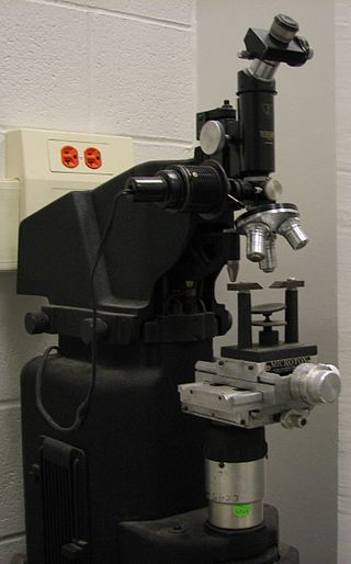
The Vickers hardness test was developed in 1921 by Robert L. Smith and George E. Sandland at Vickers Ltd as an alternative to the Brinell method to measure the hardness of materials. The Vickers test is often easier to use than other hardness tests since the required calculations are independent of the size of the indenter, and the indenter can be used for all materials irrespective of hardness. The basic principle, as with all common measures of hardness, is to observe a material's ability to resist plastic deformation from a standard source. The Vickers test can be used for all metals and has one of the widest scales among hardness tests. The unit of hardness given by the test is known as the Vickers Pyramid Number (HV) or Diamond Pyramid Hardness (DPH). The hardness number can be converted into units of pascals, but should not be confused with pressure, which uses the same units. The hardness number is determined by the load over the surface area of the indentation and not the area normal to the force, and is therefore not pressure.

Work hardening, also known as strain hardening, is the process by which a material's load-bearing capacity (strength) increases during plastic (permanent) deformation. This characteristic is what sets ductile materials apart from brittle materials. Work hardening may be desirable, undesirable, or inconsequential, depending on the application.

In engineering, shear strength is the strength of a material or component against the type of yield or structural failure when the material or component fails in shear. A shear load is a force that tends to produce a sliding failure on a material along a plane that is parallel to the direction of the force. When a paper is cut with scissors, the paper fails in shear.
In the field of solid mechanics, torsion is the twisting of an object due to an applied torque. Torsion is expressed in either the pascal (Pa), an SI unit for newtons per square metre, or in pounds per square inch (psi) while torque is expressed in newton metres (N·m) or foot-pound force (ft·lbf). In sections perpendicular to the torque axis, the resultant shear stress in this section is perpendicular to the radius.
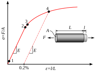
In materials science and engineering, the yield point is the point on a stress–strain curve that indicates the limit of elastic behavior and the beginning of plastic behavior. Below the yield point, a material will deform elastically and will return to its original shape when the applied stress is removed. Once the yield point is passed, some fraction of the deformation will be permanent and non-reversible and is known as plastic deformation.
A36 steel is a common structural steel alloy used in the United States. The A36 standard was established by the ASTM International. The standard was published in 1960 and has been updated several times since. Prior to 1960, the dominant standards for structural steel in North America were A7 and A9. Note that SAE/AISI A7 and A9 tool steels are not the same as the obsolete ASTM A7 and A9 structural steels.

Anchor bolts are used to connect structural and non-structural elements to concrete. The connection can be made by a variety of different components: anchor bolts, steel plates, or stiffeners. Anchor bolts transfer different types of load: tension forces and shear forces.

A screw is an externally helical threaded fastener capable of being tightened or released by a twisting force (torque) to the head. The most common uses of screws are to hold objects together and there are many forms for a variety of materials. Screws might be inserted into holes in assembled parts or a screw may form its own thread. The difference between a screw and a bolt is that the latter is designed to be tightened or released by torquing a nut.

The plane strain compression test is a specialized test used on some materials ranging from metals to soils.

Structural engineering depends upon a detailed knowledge of loads, physics and materials to understand and predict how structures support and resist self-weight and imposed loads. To apply the knowledge successfully structural engineers will need a detailed knowledge of mathematics and of relevant empirical and theoretical design codes. They will also need to know about the corrosion resistance of the materials and structures, especially when those structures are exposed to the external environment.
ASTM A325 is an ASTM International standard for heavy hex structural bolts, titled Standard Specification for Structural Bolts, Steel, Heat Treated, 120/105 ksi Minimum Tensile Strength. It defines mechanical properties for bolts that range from 1⁄2 to 1+1⁄2 inches in diameter.
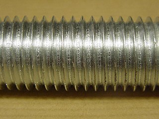
A threaded rod, also known as a stud, is a relatively long rod that is threaded on both ends; the thread may extend along the complete length of the rod. They are designed to be used in tension. Threaded rod in bar stock form is often called all-thread (ATR); other names include fully-threaded rod, redi-rod, continuously-threaded rod, and TFL rod.
Most of the terms listed in Wikipedia glossaries are already defined and explained within Wikipedia itself. However, glossaries like this one are useful for looking up, comparing and reviewing large numbers of terms together. You can help enhance this page by adding new terms or writing definitions for existing ones.

