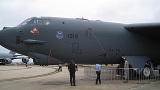
Structural analysis is a branch of solid mechanics which uses simplified models for solids like bars, beams and shells for engineering decision making. Its main objective is to determine the effect of loads on the physical structures and their components. In contrast to theory of elasticity, the models used in structure analysis are often differential equations in one spatial variable. Structures subject to this type of analysis include all that must withstand loads, such as buildings, bridges, aircraft and ships. Structural analysis uses ideas from applied mechanics, materials science and applied mathematics to compute a structure's deformations, internal forces, stresses, support reactions, velocity, accelerations, and stability. The results of the analysis are used to verify a structure's fitness for use, often precluding physical tests. Structural analysis is thus a key part of the engineering design of structures.

A truss is an assembly of members such as beams, connected by nodes, that creates a rigid structure.
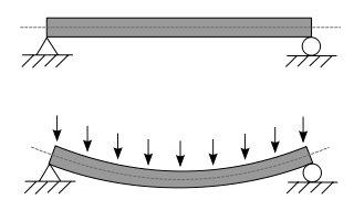
A beam is a structural element that primarily resists loads applied laterally across the beam's axis. Its mode of deflection is primarily by bending, as loads produce reaction forces at the beam's support points and internal bending moments, shear, stresses, strains, and deflections. Beams are characterized by their manner of support, profile, equilibrium conditions, length, and material.
In structural engineering, buckling is the sudden change in shape (deformation) of a structural component under load, such as the bowing of a column under compression or the wrinkling of a plate under shear. If a structure is subjected to a gradually increasing load, when the load reaches a critical level, a member may suddenly change shape and the structure and component is said to have buckled. Euler's critical load and Johnson's parabolic formula are used to determine the buckling stress of a column.
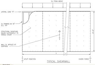
In structural engineering, a shear wall is a two-dimensional vertical element of a system that is designed to resist in-plane lateral forces, typically wind and seismic loads.

Steel frame is a building technique with a "skeleton frame" of vertical steel columns and horizontal I-beams, constructed in a rectangular grid to support the floors, roof and walls of a building which are all attached to the frame. The development of this technique made the construction of the skyscraper possible. Steel frame has displaced its predecessor, the iron frame, in the early 20th century.

Plastic bending is a nonlinear behavior particular to members made of ductile materials that frequently achieve much greater ultimate bending strength than indicated by a linear elastic bending analysis. In both the plastic and elastic bending analyses of a straight beam, it is assumed that the strain distribution is linear about the neutral axis. In an elastic analysis this assumption leads to a linear stress distribution but in a plastic analysis the resulting stress distribution is nonlinear and is dependent on the beam's material.

Portal frame is a construction technique where vertical supports are connected to horizontal beams or trusses via fixed joints with designed-in moment-resisting capacity. The result is wide spans and open floors.
The staggered truss system is a type of structural steel framing used in high-rise buildings. The system consists of a series of story-high trusses spanning the total width between two rows of exterior columns and arranged in a staggered pattern on adjacent column lines. William LeMessurier, the founder Cambridge, Massachusetts engineering firm LeMessurier Consultants has been credited in developing this award winning system as part of his research at the Massachusetts Institute of Technology.
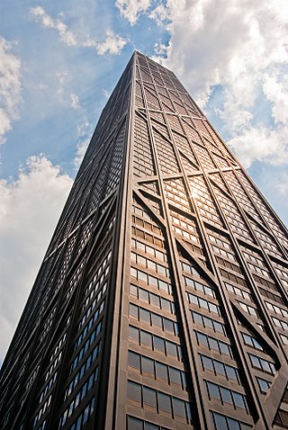
In structural engineering, the tube is a system where, to resist lateral loads, a building is designed to act like a hollow cylinder, cantilevered perpendicular to the ground. This system was introduced by Fazlur Rahman Khan while at the architectural firm Skidmore, Owings & Merrill (SOM), in their Chicago office. The first example of the tube's use is the 43-story Khan-designed DeWitt-Chestnut Apartment Building, since renamed Plaza on DeWitt, in Chicago, Illinois, finished in 1966.
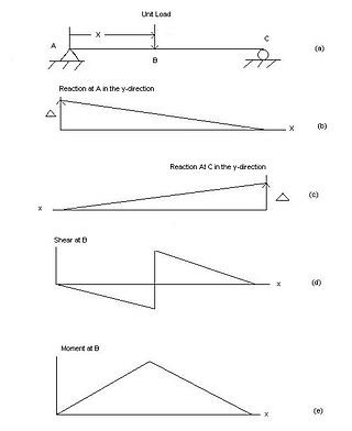
In engineering, an influence line graphs the variation of a function at a specific point on a beam or truss caused by a unit load placed at any point along the structure. Common functions studied with influence lines include reactions, shear, moment, and deflection (Deformation). Influence lines are important in designing beams and trusses used in bridges, crane rails, conveyor belts, floor girders, and other structures where loads will move along their span. The influence lines show where a load will create the maximum effect for any of the functions studied.
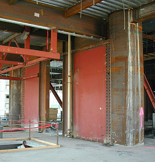
A steel plate shear wall (SPSW) consists of steel infill plates bounded by boundary elements.
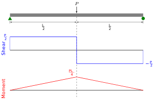
Shear force and bending moment diagrams are analytical tools used in conjunction with structural analysis to help perform structural design by determining the value of shear forces and bending moments at a given point of a structural element such as a beam. These diagrams can be used to easily determine the type, size, and material of a member in a structure so that a given set of loads can be supported without structural failure. Another application of shear and moment diagrams is that the deflection of a beam can be easily determined using either the moment area method or the conjugate beam method.

In structural engineering, deflection is the degree to which a part of a long structural element is deformed laterally under a load. It may be quantified in terms of an angle or a distance . A longitudinal deformation is called elongation.

The history of structural engineering dates back to at least 2700 BC when the step pyramid for Pharaoh Djoser was built by Imhotep, the first architect in history known by name. Pyramids were the most common major structures built by ancient civilizations because it is a structural form which is inherently stable and can be almost infinitely scaled.

Earthquake-resistant or aseismic structures are designed to protect buildings to some or greater extent from earthquakes. While no structure can be entirely impervious to earthquake damage, the goal of earthquake engineering is to erect structures that fare better during seismic activity than their conventional counterparts. According to building codes, earthquake-resistant structures are intended to withstand the largest earthquake of a certain probability that is likely to occur at their location. This means the loss of life should be minimized by preventing collapse of the buildings for rare earthquakes while the loss of the functionality should be limited for more frequent ones.
Mete Avni Sözen was Kettelhut Distinguished Professor of Structural Engineering at Purdue University, Indiana, United States from 1992 to 2018.
Moment-resisting frame is a rectilinear assemblage of beams and columns, with the beams rigidly connected to the columns.
In mechanics, the neutral plane or neutral surface is a conceptual plane within a beam or cantilever. When loaded by a bending force, the beam bends so that the inner surface is in compression and the outer surface is in tension. The neutral plane is the surface within the beam between these zones, where the material of the beam is not under stress, either compression or tension.
A structural support is a part of a building or structure that provides the necessary stiffness and strength in order to resist the internal forces and guide them safely to the ground. External loads that act on buildings cause internal forces in building support structures. Supports can be either at the end or at any intermediate point along a structural member or a constituent part of a building and they are referred to as connections, joints or restraints.