This article needs additional citations for verification .(September 2008) |

In engineering, deformation (the change in size or shape of an object) may be elastic or plastic. If the deformation is negligible, the object is said to be rigid.
This article needs additional citations for verification .(September 2008) |
In engineering, deformation (the change in size or shape of an object) may be elastic or plastic. If the deformation is negligible, the object is said to be rigid.
Occurrence of deformation in engineering applications is based on the following background concepts:
The relationship between stress and strain is generally linear and reversible up until the yield point and the deformation is elastic. Elasticity in materials occurs when applied stress does not surpass the energy required to break molecular bonds, allowing the material to deform reversibly and return to its original shape once the stress is removed. The linear relationship for a material is known as Young's modulus. Above the yield point, some degree of permanent distortion remains after unloading and is termed plastic deformation. The determination of the stress and strain throughout a solid object is given by the field of strength of materials and for a structure by structural analysis.
In the above figure, it can be seen that the compressive loading (indicated by the arrow) has caused deformation in the cylinder so that the original shape (dashed lines) has changed (deformed) into one with bulging sides. The sides bulge because the material, although strong enough to not crack or otherwise fail, is not strong enough to support the load without change. As a result, the material is forced out laterally. Internal forces (in this case at right angles to the deformation) resist the applied load.
Depending on the type of material, size and geometry of the object, and the forces applied, various types of deformation may result. The image to the right shows the engineering stress vs. strain diagram for a typical ductile material such as steel. Different deformation modes may occur under different conditions, as can be depicted using a deformation mechanism map.
Permanent deformation is irreversible; the deformation stays even after removal of the applied forces, while the temporary deformation is recoverable as it disappears after the removal of applied forces. Temporary deformation is also called elastic deformation, while the permanent deformation is called plastic deformation.

The study of temporary or elastic deformation in the case of engineering strain is applied to materials used in mechanical and structural engineering, such as concrete and steel, which are subjected to very small deformations. Engineering strain is modeled by infinitesimal strain theory, also called small strain theory, small deformation theory, small displacement theory, or small displacement-gradient theory where strains and rotations are both small.
For some materials, e.g. elastomers and polymers, subjected to large deformations, the engineering definition of strain is not applicable, e.g. typical engineering strains greater than 1%, [1] thus other more complex definitions of strain are required, such as stretch, logarithmic strain, Green strain, and Almansi strain. Elastomers and shape memory metals such as Nitinol exhibit large elastic deformation ranges, as does rubber. However, elasticity is nonlinear in these materials.
Normal metals, ceramics and most crystals show linear elasticity and a smaller elastic range.
Linear elastic deformation is governed by Hooke's law, which states:
where
This relationship only applies in the elastic range and indicates that the slope of the stress vs. strain curve can be used to find Young's modulus (E). Engineers often use this calculation in tensile tests. The area under this elastic region is known as resilience.
Note that not all elastic materials undergo linear elastic deformation; some, such as concrete, gray cast iron, and many polymers, respond in a nonlinear fashion. For these materials Hooke's law is inapplicable. [2]

This type of deformation is not undone simply by removing the applied force. An object in the plastic deformation range, however, will first have undergone elastic deformation, which is undone simply be removing the applied force, so the object will return part way to its original shape. Soft thermoplastics have a rather large plastic deformation range as do ductile metals such as copper, silver, and gold. Steel does, too, but not cast iron. Hard thermosetting plastics, rubber, crystals, and ceramics have minimal plastic deformation ranges. An example of a material with a large plastic deformation range is wet chewing gum, which can be stretched to dozens of times its original length.
Under tensile stress, plastic deformation is characterized by a strain hardening region and a necking region and finally, fracture (also called rupture). During strain hardening the material becomes stronger through the movement of atomic dislocations. The necking phase is indicated by a reduction in cross-sectional area of the specimen. Necking begins after the ultimate strength is reached. During necking, the material can no longer withstand the maximum stress and the strain in the specimen rapidly increases. Plastic deformation ends with the fracture of the material.

Usually, compressive stress applied to bars, columns, etc. leads to shortening.
Loading a structural element or specimen will increase the compressive stress until it reaches its compressive strength. According to the properties of the material, failure modes are yielding for materials with ductile behavior (most metals, some soils and plastics) or rupturing for brittle behavior (geomaterials, cast iron, glass, etc.).
In long, slender structural elements — such as columns or truss bars — an increase of compressive force F leads to structural failure due to buckling at lower stress than the compressive strength.
A break occurs after the material has reached the end of the elastic, and then plastic, deformation ranges. At this point forces accumulate until they are sufficient to cause a fracture. All materials will eventually fracture, if sufficient forces are applied.
Engineering stress and engineering strain are approximations to the internal state that may be determined from the external forces and deformations of an object, provided that there is no significant change in size. When there is a significant change in size, the true stress and true strain can be derived from the instantaneous size of the object.
Consider a bar of original cross sectional area A0 being subjected to equal and opposite forces F pulling at the ends so the bar is under tension. The material is experiencing a stress defined to be the ratio of the force to the cross sectional area of the bar, as well as an axial elongation:
| Stress | Strain |
|---|---|
Subscript 0 denotes the original dimensions of the sample. The SI derived unit for stress is newtons per square metre, or pascals (1 pascal = 1 Pa = 1 N/m2), and strain is unitless. The stress–strain curve for this material is plotted by elongating the sample and recording the stress variation with strain until the sample fractures. By convention, the strain is set to the horizontal axis and stress is set to vertical axis. Note that for engineering purposes we often assume the cross-section area of the material does not change during the whole deformation process. This is not true since the actual area will decrease while deforming due to elastic and plastic deformation. The curve based on the original cross-section and gauge length is called the engineering stress–strain curve, while the curve based on the instantaneous cross-section area and length is called the true stress–strain curve. Unless stated otherwise, engineering stress–strain is generally used.

In the above definitions of engineering stress and strain, two behaviors of materials in tensile tests are ignored:
True stress and true strain are defined differently than engineering stress and strain to account for these behaviors. They are given as
| Stress | Strain |
|---|---|
Here the dimensions are instantaneous values. Assuming volume of the sample conserves and deformation happens uniformly,
The true stress and strain can be expressed by engineering stress and strain. For true stress,
For the strain,
Integrate both sides and apply the boundary condition,
So in a tension test, true stress is larger than engineering stress and true strain is less than engineering strain. Thus, a point defining true stress–strain curve is displaced upwards and to the left to define the equivalent engineering stress–strain curve. The difference between the true and engineering stresses and strains will increase with plastic deformation. At low strains (such as elastic deformation), the differences between the two is negligible. As for the tensile strength point, it is the maximal point in engineering stress–strain curve but is not a special point in true stress–strain curve. Because engineering stress is proportional to the force applied along the sample, the criterion for necking formation can be set as
This analysis suggests nature of the ultimate tensile strength (UTS) point. The work strengthening effect is exactly balanced by the shrinking of section area at UTS point.
After the formation of necking, the sample undergoes heterogeneous deformation, so equations above are not valid. The stress and strain at the necking can be expressed as:
An empirical equation is commonly used to describe the relationship between true stress and true strain.
Here, n is the strain-hardening exponent and K is the strength coefficient. n is a measure of a material's work hardening behavior. Materials with a higher n have a greater resistance to necking. Typically, metals at room temperature have n ranging from 0.02 to 0.5. [3]
Since we disregard the change of area during deformation above, the true stress and strain curve should be re-derived. For deriving the stress strain curve, we can assume that the volume change is 0 even if we deformed the materials. We can assume that:
Then, the true stress can be expressed as below:
Additionally, the true strain εT can be expressed as below:
Then, we can express the value as
Thus, we can induce the plot in terms of and as right figure.
Additionally, based on the true stress-strain curve, we can estimate the region where necking starts to happen. Since necking starts to appear after ultimate tensile stress where the maximum force applied, we can express this situation as below:
so this form can be expressed as below:
It indicates that the necking starts to appear where reduction of area becomes much significant compared to the stress change. Then the stress will be localized to specific area where the necking appears.
Additionally, we can induce various relation based on true stress-strain curve.
1) True strain and stress curve can be expressed by the approximate linear relationship by taking a log on true stress and strain. The relation can be expressed as below:
Where is stress coefficient and is strain-hardening coefficient. Usually, the value of has range around 0.02 to 0.5 at room temperature. If is 1, we can express this material as perfect elastic material. [4] [5]
2) In reality, stress is also highly dependent on the rate of strain variation. Thus, we can induce the empirical equation based on the strain rate variation.

Where is constant related to the material flow stress. indicates the derivative of strain by the time, which is also known as strain rate. is the strain-rate sensitivity. Moreover, value of is related to the resistance toward the necking. Usually, the value of is at the range of 0-0.1 at room temperature and as high as 0.8 when the temperature is increased.
By combining the 1) and 2), we can create the ultimate relation as below:
Where is the global constant for relating strain, strain rate and stress.
3) Based on the true stress-strain curve and its derivative form, we can estimate the strain necessary to start necking. This can be calculated based on the intersection between true stress-strain curve as shown in right.
This figure also shows the dependency of the necking strain at different temperature. In case of FCC metals, both of the stress-strain curve at its derivative are highly dependent on temperature. Therefore, at higher temperature, necking starts to appear even under lower strain value.
All of these properties indicate the importance of calculating the true stress-strain curve for further analyzing the behavior of materials in sudden environment.
4) A graphical method, so-called "Considere construction", can help determine the behavior of stress-strain curve whether necking or drawing happens on the sample. By setting as determinant, the true stress and strain can be expressed with engineering stress and strain as below:
Therefore, the value of engineering stress can be expressed by the secant line from made by true stress and value where to . By analyzing the shape of diagram and secant line, we can determine whether the materials show drawing or necking.

On the figure (a), there is only concave upward Considere plot. It indicates that there is no yield drop so the material will be suffered from fracture before it yields. On the figure (b), there is specific point where the tangent matches with secant line at point where . After this value, the slope becomes smaller than the secant line where necking starts to appear. On the figure (c), there is point where yielding starts to appear but when , the drawing happens. After drawing, all the material will stretch and eventually show fracture. Between and , the material itself does not stretch but rather, only the neck starts to stretch out.
A popular misconception is that all materials that bend are "weak" and those that do not are "strong". In reality, many materials that undergo large elastic and plastic deformations, such as steel, are able to absorb stresses that would cause brittle materials, such as glass, with minimal plastic deformation ranges, to break. [7]
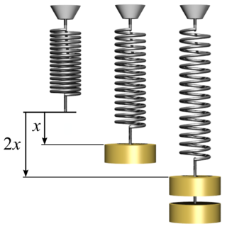
In physics, Hooke's law is an empirical law which states that the force needed to extend or compress a spring by some distance scales linearly with respect to that distance—that is, Fs = kx, where k is a constant factor characteristic of the spring, and x is small compared to the total possible deformation of the spring. The law is named after 17th-century British physicist Robert Hooke. He first stated the law in 1676 as a Latin anagram. He published the solution of his anagram in 1678 as: ut tensio, sic vis. Hooke states in the 1678 work that he was aware of the law since 1660.

In engineering and materials science, a stress–strain curve for a material gives the relationship between stress and strain. It is obtained by gradually applying load to a test coupon and measuring the deformation, from which the stress and strain can be determined. These curves reveal many of the properties of a material, such as the Young's modulus, the yield strength and the ultimate tensile strength.

In materials science and solid mechanics, Poisson's ratio is a measure of the Poisson effect, the deformation of a material in directions perpendicular to the specific direction of loading. The value of Poisson's ratio is the negative of the ratio of transverse strain to axial strain. For small values of these changes, ν is the amount of transversal elongation divided by the amount of axial compression. Most materials have Poisson's ratio values ranging between 0.0 and 0.5. For soft materials, such as rubber, where the bulk modulus is much higher than the shear modulus, Poisson's ratio is near 0.5. For open-cell polymer foams, Poisson's ratio is near zero, since the cells tend to collapse in compression. Many typical solids have Poisson's ratios in the range of 0.2 to 0.3. The ratio is named after the French mathematician and physicist Siméon Poisson.
Linear elasticity is a mathematical model as to how solid objects deform and become internally stressed by prescribed loading conditions. It is a simplification of the more general nonlinear theory of elasticity and a branch of continuum mechanics.

In mechanics, compressive strength is the capacity of a material or structure to withstand loads tending to reduce size (compression). It is opposed to tensile strength which withstands loads tending to elongate, resisting tension. In the study of strength of materials, compressive strength, tensile strength, and shear strength can be analyzed independently.
A Newtonian fluid is a fluid in which the viscous stresses arising from its flow are at every point linearly correlated to the local strain rate — the rate of change of its deformation over time. Stresses are proportional to the rate of change of the fluid's velocity vector.
A Maxwell material is the most simple model viscoelastic material showing properties of a typical liquid. It shows viscous flow on the long timescale, but additional elastic resistance to fast deformations. It is named for James Clerk Maxwell who proposed the model in 1867. It is also known as a Maxwell fluid. A generalization of the scalar relation to a tensor equation lacks motivation from more microscopic models and does not comply with the concept of material objectivity. However, these criteria are fulfilled by the Upper-convected Maxwell model.
In materials science and continuum mechanics, viscoelasticity is the property of materials that exhibit both viscous and elastic characteristics when undergoing deformation. Viscous materials, like water, resist both shear flow and strain linearly with time when a stress is applied. Elastic materials strain when stretched and immediately return to their original state once the stress is removed.
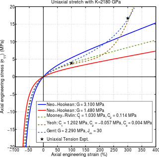
A neo-Hookean solid is a hyperelastic material model, similar to Hooke's law, that can be used for predicting the nonlinear stress–strain behavior of materials undergoing large deformations. The model was proposed by Ronald Rivlin in 1948 using invariants, though Mooney had already described a version in stretch form in 1940, and Wall had noted the equivalence in shear with the Hooke model in 1942.
In engineering and materials science, necking is a mode of tensile deformation where relatively large amounts of strain localize disproportionately in a small region of the material. The resulting prominent decrease in local cross-sectional area provides the basis for the name "neck". Because the local strains in the neck are large, necking is often closely associated with yielding, a form of plastic deformation associated with ductile materials, often metals or polymers. Once necking has begun, the neck becomes the exclusive location of yielding in the material, as the reduced area gives the neck the largest local stress.
Elastic energy is the mechanical potential energy stored in the configuration of a material or physical system as it is subjected to elastic deformation by work performed upon it. Elastic energy occurs when objects are impermanently compressed, stretched or generally deformed in any manner. Elasticity theory primarily develops formalisms for the mechanics of solid bodies and materials. The elastic potential energy equation is used in calculations of positions of mechanical equilibrium. The energy is potential as it will be converted into other forms of energy, such as kinetic energy and sound energy, when the object is allowed to return to its original shape (reformation) by its elasticity.
The J-integral represents a way to calculate the strain energy release rate, or work (energy) per unit fracture surface area, in a material. The theoretical concept of J-integral was developed in 1967 by G. P. Cherepanov and independently in 1968 by James R. Rice, who showed that an energetic contour path integral was independent of the path around a crack.
A hyperelastic or Green elastic material is a type of constitutive model for ideally elastic material for which the stress–strain relationship derives from a strain energy density function. The hyperelastic material is a special case of a Cauchy elastic material.
The Ramberg–Osgood equation was created to describe the nonlinear relationship between stress and strain—that is, the stress–strain curve—in materials near their yield points. It is especially applicable to metals that harden with plastic deformation, showing a smooth elastic-plastic transition. As it is a phenomenological model, checking the fit of the model with actual experimental data for the particular material of interest is essential.

Critical state soil mechanics is the area of soil mechanics that encompasses the conceptual models representing the mechanical behavior of saturated remoulded soils based on the critical state concept. At the critical state, the relationship between forces applied in the soil (stress), and the resulting deformation resulting from this stress (strain) becomes constant. The soil will continue to deform, but the stress will no longer increase.
The Larson–Miller relation, also widely known as the Larson–Miller parameter and often abbreviated LMP, is a parametric relation used to extrapolate experimental data on creep and rupture life of engineering materials.

Viscoplasticity is a theory in continuum mechanics that describes the rate-dependent inelastic behavior of solids. Rate-dependence in this context means that the deformation of the material depends on the rate at which loads are applied. The inelastic behavior that is the subject of viscoplasticity is plastic deformation which means that the material undergoes unrecoverable deformations when a load level is reached. Rate-dependent plasticity is important for transient plasticity calculations. The main difference between rate-independent plastic and viscoplastic material models is that the latter exhibit not only permanent deformations after the application of loads but continue to undergo a creep flow as a function of time under the influence of the applied load.
In mechanics, strain is defined as relative deformation, compared to a reference position configuration. Different equivalent choices may be made for the expression of a strain field depending on whether it is defined with respect to the initial or the final configuration of the body and on whether the metric tensor or its dual is considered.

In geotechnical engineering, rock mass plasticity is the study of the response of rocks to loads beyond the elastic limit. Historically, conventional wisdom has it that rock is brittle and fails by fracture, while plasticity is identified with ductile materials such as metals. In field-scale rock masses, structural discontinuities exist in the rock indicating that failure has taken place. Since the rock has not fallen apart, contrary to expectation of brittle behavior, clearly elasticity theory is not the last word.
Flow plasticity is a solid mechanics theory that is used to describe the plastic behavior of materials. Flow plasticity theories are characterized by the assumption that a flow rule exists that can be used to determine the amount of plastic deformation in the material.
{{cite book}}: CS1 maint: multiple names: authors list (link)


