Truss bridge for a single-track railway, converted to pedestrian use and pipeline support. In this example the truss is a group of triangular units supporting the bridge.Typical detail of a steel truss, which is considered as a revolute jointHistorical detail of a steel truss with an actual revolute joint
A truss is an assembly of members such as beams, connected by nodes, that creates a rigid structure.[1]
In engineering, a truss is a structure that "consists of two-force members only, where the members are organized so that the assemblage as a whole behaves as a single object".[2] A two-force member is a structural component where force is applied to only two points. Although this rigorous definition allows the members to have any shape connected in any stable configuration, architectural trusses typically comprise five or more triangular units constructed with straight members whose ends are connected at joints referred to as nodes.
In this typical context, external forces and reactions to those forces are considered to act only at the nodes and result in forces in the members that are either tensile or compressive. For straight members, moments (torques) are explicitly excluded because, and only because, all the joints in a truss are treated as revolutes, as is necessary for the links to be two-force members.
A planar truss is one where all members and nodes lie within a two-dimensional plane, while a space frame has members and nodes that extend into three dimensions. The top beams in a truss are called top chords and are typically in compression, and the bottom beams are called bottom chords and are typically in tension. The interior beams are called webs, and the areas inside the webs are called panels,[3] or from graphic statics (see Cremona diagram) polygons.[4]
Etymology
Truss derives from the Old French word trousse, from around 1200 AD, which means "collection of things bound together".[5][6] The term truss has often been used to describe any assembly of members such as a cruck frame[7][8] or a couple of rafters.[9][10]
Characteristics
An Egyptian ship with a rope truss, the oldest known use of trusses. Trusses did not come into common use until the Roman era.
A truss consists of typically (but not necessarily) straight members connected at joints, traditionally termed panel points. Trusses are typically (but not necessarily[11]) composed of triangles because of the structural stability of that shape and design. A triangle is the simplest geometric figure that will not change shape when the lengths of the sides are fixed.[12] In comparison, both the angles and the lengths of a four-sided figure must be fixed for it to retain its shape.
The simplest form of a truss is one single triangle. This type of truss is seen in a framed roof consisting of rafters and a ceiling joist,[13] and in other mechanical structures such as bicycles and aircraft. Because of the stability of this shape and the methods of analysis used to calculate the forces within it, a truss composed entirely of triangles is known as a simple truss.[14] However, a simple truss is often defined more restrictively by demanding that it can be constructed through successive addition of pairs of members, each connected to two existing joints and to each other to form a new joint, and this definition does not require a simple truss to comprise only triangles.[11] The traditional diamond-shape bicycle frame, which uses two conjoined triangles, is an example of a simple truss.[15]
Planar truss
Roof truss
A planar truss lies in a single plane.[14] Planar trusses are typically used in parallel to form roofs and bridges.[16]
The depth of a truss, or the height between the upper and lower chords, is what makes it an efficient structural form. A solid girder or beam of equal strength would have substantial weight and material cost as compared to a truss. For a given span, a deeper truss will require less material in the chords and greater material in the verticals and diagonals. An optimum depth of the truss will maximize the efficiency.[17]
Space frame truss
A space frame truss is a three-dimensional framework of members pinned at their ends. A tetrahedron shape is the simplest space truss, consisting of six members that meet at four joints.[14] Large planar structures may be composed from tetrahedrons with common edges, and they are also employed in the base structures of large free-standing power-line pylons.
A large timber Howe truss in a commercial building
There are two basic types of truss:
The pitched truss, or common truss, is characterized by its triangular shape. It is most often used for roof construction. Some common trusses are named according to their web configuration. The chord size and web configuration are determined by span, load, and spacing.
The parallel-chord truss, or flat truss, gets its name from its parallel top and bottom chords. It is often used for floor construction.
A combination of the two is a truncated truss, used in hip roof construction. A metal-plate-connected wood truss is a roof or floor truss whose wood members are connected with metal connector plates.
Truss members form a series of equilateral triangles, alternating up and down.
Octet truss
Truss members are made up of all equivalent equilateral triangles. The minimum composition is two regular tetrahedrons along with an octahedron. They fill up three-dimensional space in a variety of configurations.
Pratt truss
Tempe Salt River Southern Pacific Railroad bridge
The Pratt truss was patented in 1844 by two Boston railway engineers,[18] Caleb Pratt and his son Thomas Willis Pratt.[19] The design uses vertical members for compression and diagonal members to respond to tension. The Pratt truss design remained popular as bridge designers switched from wood to iron, and from iron to steel.[20] This continued popularity of the Pratt truss is probably due to the fact that the configuration of the members means that longer diagonal members are only in tension for gravity load effects. This allows these members to be used more efficiently, as slenderness effects related to buckling under compression loads (which are compounded by the length of the member) will typically not control the design. Therefore, for a given planar truss with a fixed depth, the Pratt configuration is usually the most efficient under static, vertical loading.
The Southern Pacific Railroad bridge in Tempe, Arizona, is a 393-meter-long (1,289ft) truss bridge built in 1912.[21][22] The structure, still in use today, consists of nine Pratt truss spans of varying lengths.
The Wright Flyer used a Pratt truss in its wing construction, as the minimization of compression member lengths allowed for lower aerodynamic drag.[23]
American architect Ithiel Town designed Town's Lattice Truss as an alternative to heavy-timber bridges. His design, patented in 1820 and 1835, uses easy-to-handle planks arranged diagonally with short spaces in between them, to form a lattice.
Bowstring truss
A bowstring truss is used on the oldest metal bridge in Virginia.
Named for their shape, bowstring trusses were first used for arched truss bridges, often confused with tied-arch bridges.
Thousands of bowstring trusses were used during World War II for holding up the curved roofs of aircraft hangars and other military buildings. Many variations exist in the arrangements of the members connecting the nodes of the upper arc with those of the lower, straight sequence of members, from nearly isosceles triangles to a variant of the Pratt truss.
One of the simplest truss styles to implement, the king post consists of two angled supports leaning into a common vertical support.
QueenPostTruss
The queen post truss, sometimes queenpost or queenspost, is similar to a king post truss in that the outer supports are angled towards the centre of the structure. The primary difference is the horizontal extension at the centre which relies on beam action to provide mechanical stability. This truss style is only suitable for relatively short spans.[24]
Queen post trusses on rail vehicles
An application of the queen post truss, once common on freight and passenger railroad vehicles – especially ones with wooden bodies – is an inversion of the design applied to bridges. Originally deployed on cars with wood frames (and on some very early steel frame cars with shallow sills) to provide strength to resist vertical deflection, the truss made the car stronger and/or lighter than the alternatives available at the time. The design was superseded when stronger, cheaper steels became available and steel centre sills were incorporated.[25]A South Australian Railways passenger car built in 1918 with queen post trusses. The queen posts are the two vertical components; the short horizontal tube at the mid-point of the truss rod is the turnbuckle, which is adjusted by rotating to achieve the desired support of the car's frame.
Lenticular trusses, patented in 1878 by William Douglas (although the Gaunless Bridge of 1823 was the first of the type), have the top and bottom chords of the truss arched, forming a lens shape. A lenticular pony truss bridge is a bridge design that involves a lenticular truss extending above and below the roadbed.
A Vierendeel bridge, which lacks diagonal elements in the primary structure
The members of a Vierendeel structure are not triangulated but form rectangular openings. The structure has a frame with fixed joints that are capable of transferring and resisting bending moments. As such, it does not fit the definition of a truss, since it contains non-two-force members: regular trusses comprise members that are commonly assumed to have pinned joints, with the implication that no moments exist at the jointed ends. This style of structure was named after the Belgian engineer Arthur Vierendeel,[26] who developed the design in 1896. It is rarely used for bridges because of higher costs compared to a triangulated truss, but in buildings it has the advantage that a large amount of the exterior envelope remains unobstructed and it can therefore be used for windows and door openings. In some applications this is preferable to a braced-frame system, which would leave some areas obstructed by the diagonal braces.
A truss that is assumed to comprise members that are connected by means of pin joints, and which is supported at both ends by means of hinged joints and rollers, is described as being statically determinate. Newton's laws apply to the structure as a whole, as well as to each node or joint. In order for any node that may be subject to an external load or force to remain static in space, the following conditions must hold: the sums of all (horizontal and vertical) forces, as well as all moments acting about the node, equal zero. Analysis of these conditions at each node yields the magnitude of the compression or tension forces.
Trusses that are supported at more than two positions are said to be statically indeterminate, and the application of Newton's Laws alone is not sufficient to determine the member forces.
In order for a truss with pin-connected members to be stable, it does not need to be entirely composed of triangles.[11] In mathematical terms, the following necessary condition for stability of a simple truss exists:
where m is the total number of truss members, j is the total number of joints and r is the number of reactions (equal to 3 generally) in a 2-dimensional structure.
When , the truss is said to be statically determinate, because the m+3 internal member forces and support reactions can then be completely determined by 2jequilibrium equations, once the external loads and the geometry of the truss are known. Given a certain number of joints, this is the minimum number of members, in the sense that if any member is taken out (or fails), then the truss as a whole fails. While the relation (a) is necessary, it is not sufficient for stability, which also depends on the truss geometry, support conditions and the load carrying capacity of the members.
Some structures are built with more than this minimum number of truss members. Those structures may survive even when some of the members fail. Their member forces depend on the relative stiffness of the members, in addition to the equilibrium condition described.
Because the forces in each of its two main girders are essentially planar, a truss is usually modeled as a two-dimensional plane frame. However, if there are significant out-of-plane forces, then the structure must be modeled as a three-dimensional space.
The analysis of trusses often assumes that loads are applied to joints only and not at intermediate points along the members. The weight of the members is often insignificant compared to the applied loads and so is often omitted; alternatively, half of the weight of each member may be applied to its two end joints. Provided that the members are long and slender, the moments transmitted through the joints are negligible, and the junctions can be treated as "hinges" or "pin-joints".
Under these simplifying assumptions, every member of the truss is then subjected to pure compression or pure tension forces – shear, bending moment, and other more-complex stresses are all practically zero. Trusses are physically stronger than other ways of arranging structural elements, because nearly every material can resist a much larger load in tension or compression than in shear, bending, torsion, or other kinds of force.
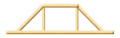
Illustrated is a simple, statically determinate flat truss with 9 joints and (2 x 9) − 3 = 15 members. External loads are concentrated in the outer joints. Since this is a symmetrical truss with symmetrical vertical loads, the reactive forces at A and B are vertical, equal, and half the total load.
The internal forces in the members of the truss can be calculated in a variety of ways, including graphical methods:
A truss can be thought of as a beam where the web consists of a series of separate members instead of a continuous plate. In the truss, the lower horizontal member (the bottom chord) and the upper horizontal member (the top chord) carry tension and compression, fulfilling the same function as the flanges of an I-beam. Which chord carries tension and which carries compression depends on the overall direction of bending. In the truss pictured above right, the bottom chord is in tension, and the top chord in compression.
The diagonal and vertical members form the truss web, and carry the shear stress. Individually, they are also in tension and compression; the exact arrangement of forces depends on the type of truss and again on the direction of bending. In the truss shown above right, the vertical members are in tension, and the diagonals are in compression.
Truss sections stabilize this building under construction in Shanghai and will house mechanical floors.
In addition to carrying the static forces, the members serve additional functions of stabilizing each other, preventing buckling. In the adjacent picture, the top chord is prevented from buckling by the presence of bracing and by the stiffness of the web members.
The inclusion of the elements shown is largely an engineering decision based upon economics, being a balance between the costs of raw materials, off-site fabrication, component transportation, on-site erection, the availability of machinery, and the cost of labor. In other cases the appearance of the structure may take on greater importance and so influence the design decisions beyond mere matters of economics. Modern materials such as prestressed concrete and fabrication methods such as automated welding have significantly influenced the design of modern bridges.
Once the force on each member is known, the next step is to determine the cross section of the individual truss members. For members under tension the cross-sectional area A can be found using A = F × γ / σy, where F is the force in the member, γ is a safety factor (typically 1.5 but dependent on building codes), and σy is the yield tensile strength of the steel used.
The members under compression also have to be designed to be safe against buckling.
The weight of a truss member depends directly on its cross section—that weight partially determines how strong the other members of the truss need to be. Giving one member a larger cross section than on a previous iteration requires giving other members a larger cross section as well, to hold the greater weight of the first member—one needs to go through another iteration to find exactly how much greater the other members need to be. Sometimes the designer goes through several iterations of the design process to converge on the "right" cross section for each member. On the other hand, reducing the size of one member from the previous iteration merely makes the other members have a larger (and more expensive) safety factor than is technically necessary, but does not require another iteration to find a buildable truss.
The effect of the weight of the individual truss members in a large truss, such as a bridge, is usually insignificant compared to the force of the external loads.
Design of joints
After determining the minimum cross section of the members, the last step in the design of a truss would be detailing of the bolted joints, e.g., involving shear stress of the bolt connections used in the joints. Based on the needs of the project, truss internal connections (joints) can be designed as rigid, semi-rigid, or hinged. Rigid connections can allow transfer of bending moments, leading to development of secondary bending moments in the members.
Component connections are critical to the structural integrity of a framing system. In buildings with large, clearspan wood trusses, the most critical connections are those between the truss and its supports. In addition to gravity-induced forces (a.k.a. bearing loads), these connections must resist shear forces acting perpendicular to the plane of the truss and uplift forces due to wind. Depending upon overall building design, the connections may also be required to transfer bending moment.
Wood posts enable the fabrication of strong, direct, yet inexpensive connections between large trusses and walls. Exact details for post-to-truss connections vary from designer to designer, and may be influenced by post type. Solid-sawn timber and glulam posts are generally notched to form a truss-bearing surface. The truss is rested on the notches and bolted into place. A special plate/bracket may be added to increase connection load-transfer capabilities. With mechanically-laminated posts, the truss may rest on a shortened outer-ply or on a shortened inner-ply. The later scenario places the bolts in double shear and is a very effective connection.
↑Plesha, Michael E.; Gray, Gary L.; Costanzo, Francesco (2013). Engineering Mechanics: Statics (2nded.). New York: McGraw-Hill Companies Inc. pp.364–407. ISBN978-0-07-338029-2.
↑Ching, Frank. A Visual Dictionary of Architecture. 2nd ed. Hoboken, N.J.: Wiley, 2012. 277. Print. ISBN9780470648858
↑Bow R. H., Economics of construction in relation to framed structures. Spon, London, 1873
↑Noble, Allen George. Traditional buildings a global survey of structural forms and cultural functions. London: I.B. Tauris; 2007. 115. ISBN1845113055
↑Davies, Nikolas, and Erkki Jokiniemi. Dictionary of architecture and building construction. Amsterdam: Elsevier/Architectural Press, 2008. 394. ISBN0750685026
↑Davies, Nikolas, and Erkki Jokiniemi. Architect's illustrated pocket dictionary. Oxford: Architectural Press, 2011. 121. ISBN0080965377
↑Crabb, George. Universal Technological Dictionary Or Familiar Explanation of the Terms used in All Arts and Sciences...", Volume 1 London: 1823. Couples.
123Beer, Ferd; Johnston, Russ (2013). Vector Mechanics for Engineers: Statics (10thed.). New York, NY: McGraw-Hill. pp.285–313. ISBN978-0-07-740228-0.
↑Maginnis, Owen Bernard (1903). Roof Framing Made Easy (2nded.). New York: The Industrial Publication Company. p.9. Retrieved 2008-08-16.
123Hibbeler, Russell Charles (1983) [1974]. Engineering Mechanics-Statics (3rded.). New York: Macmillan Publishing Co., Inc. pp.199–224. ISBN0-02-354310-8.
↑Wingerter, R., and Labossiere, P., ME 354, Mechanics of Materials Laboratory: Structures, University of Washington (February 2004), p.1
↑Merriman, Mansfield (1912) [192]. American Civil Engineers' Pocket Book. New York: J. Wiley & Sons. p.785. Retrieved 2008-08-16. The Economic Depth of a Truss is that which makes the material in a bridge a minimum.
This page is based on this Wikipedia article Text is available under the CC BY-SA 4.0 license; additional terms may apply. Images, videos and audio are available under their respective licenses.