Related Research Articles

An analog computer or analogue computer is a type of computer that uses the continuous variation aspect of physical phenomena such as electrical, mechanical, or hydraulic quantities to model the problem being solved. In contrast, digital computers represent varying quantities symbolically and by discrete values of both time and amplitude.
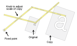
A pantograph is a mechanical linkage connected in a manner based on parallelograms so that the movement of one pen, in tracing an image, produces identical movements in a second pen. If a line drawing is traced by the first point, an identical, enlarged, or miniaturized copy will be drawn by a pen fixed to the other. Using the same principle, different kinds of pantographs are used for other forms of duplication in areas such as sculpting, minting, engraving, and milling.

A cam is a rotating or sliding piece in a mechanical linkage used especially in transforming rotary motion into linear motion. It is often a part of a rotating wheel or shaft that strikes a lever at one or more points on its circular path. The cam can be a simple tooth, as is used to deliver pulses of power to a steam hammer, for example, or an eccentric disc or other shape that produces a smooth reciprocating motion in the follower, which is a lever making contact with the cam. A cam timer is similar, and were widely used for electric machine control before the advent of inexpensive electronics, microcontrollers, integrated circuits, programmable logic controllers and digital control.

Computer-aided manufacturing (CAM) also known as computer-aided modeling or computer-aided machining is the use of software to control machine tools in the manufacturing of work pieces. This is not the only definition for CAM, but it is the most common. It may also refer to the use of a computer to assist in all operations of a manufacturing plant, including planning, management, transportation and storage. Its primary purpose is to create a faster production process and components and tooling with more precise dimensions and material consistency, which in some cases, uses only the required amount of raw material, while simultaneously reducing energy consumption. CAM is now a system used in schools and lower educational purposes. CAM is a subsequent computer-aided process after computer-aided design (CAD) and sometimes computer-aided engineering (CAE), as the model generated in CAD and verified in CAE can be input into CAM software, which then controls the machine tool. CAM is used in many schools alongside CAD to create objects.

A machinist is a tradesperson or trained professional who operates machine tools, and has the ability to set up tools such as milling machines, grinders, lathes, and drilling machines.

Machining is a manufacturing process whereby a desired shape or part is achieved by the controlled removal of material from a larger piece of raw material by cutting; it is most often performed with metal material. These processes are collectively called subtractive manufacturing, which utilizes machine tools, in contrast to additive manufacturing, which uses controlled addition of material.
In machining, numerical control, also called computer numerical control (CNC), is the automated control of tools by means of a computer. It is used to operate tools such as drills, lathes, mills, grinders, routers and 3D printers. CNC transforms a piece of material into a specified shape by following coded programmed instructions and without a manual operator directly controlling the machining operation.
A grinding dresser or wheel dresser is a tool to dress the surface of a grinding wheel. Grinding dressers are used to return a wheel to its original round shape, to expose fresh grains for renewed cutting action, or to make a different profile on the wheel's edge. Utilizing pre-determined dressing parameters will allow the wheel to be conditioned for optimum grinding performance while truing and restoring the form simultaneously.

A Tool and Cutter Grinder is used to sharpen milling cutters and tool bits along with a host of other cutting tools.
Milling cutters are cutting tools typically used in milling machines or machining centres to perform milling operations. They remove material by their movement within the machine or directly from the cutter's shape.

A rotary table is a precision work positioning device used in metalworking. It enables the operator to drill or cut work at exact intervals around a fixed axis. Some rotary tables allow the use of index plates for indexing operations, and some can also be fitted with dividing plates that enable regular work positioning at divisions for which indexing plates are not available. A rotary fixture used in this fashion is more appropriately called a dividing head.

Pencil milling is a cleanup toolpath generated by computer-aided manufacturing (CAM) programs to machine internal corners and fillets with smaller radius tools to remove the remaining material that are inaccessible with larger tools used for previous roughing, semi-finishing, and finishing toolpaths. The name comes from the way that a pencil could naturally be drawn along these corners. It is sometimes called a rolling ball toolpath.

A spotface or spot face is a machined feature in which a certain region of the workpiece is faced, providing a smooth, flat, accurately located surface. This is especially relevant on workpieces cast or forged, where the spotface's smooth, flat, accurately located surface stands in distinction to the surrounding surface whose roughness, flatness, and location are subject to wider tolerances and thus not assured with a machining level of precision. The most common application of spotfacing is facing the area around a bolt hole where the bolt's head will sit, which is often done by cutting a shallow counterbore, just deep enough "to clean up"—that is, only enough material is removed to get down past any irregularity and thus make the surface flat. Other common applications of spotfacing involve facing a pad onto a boss, creating planar surfaces in known locations that can orient a casting or forging into position in the assembly; allow part marking such as stamping or nameplate riveting; or offer machine-finish visual appeal in spots, without the need for finishing all over (FAO).
In manufacturing, threading is the process of creating a screw thread. More screw threads are produced each year than any other machine element. There are many methods of generating threads, including subtractive methods ; deformative or transformative methods ; additive methods ; or combinations thereof.
WorkNC is a Computer aided manufacturing (CAM) software developed by Sescoi for multi-axis machining.

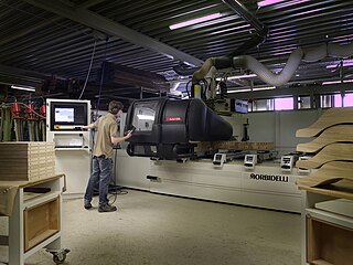
Milling is the process of machining using rotary cutters to remove material by advancing a cutter into a workpiece. This may be done by varying directions on one or several axes, cutter head speed, and pressure. Milling covers a wide variety of different operations and machines, on scales from small individual parts to large, heavy-duty gang milling operations. It is one of the most commonly used processes for machining custom parts to precise tolerances.
In forestry, a tree crown measurement is one of the tree measurements taken at the crown of a tree, which consists of the mass of foliage and branches growing outward from the trunk of the tree. The average crown spread is the average horizontal width of the crown, taken from dripline to dripline as one moves around the crown. The dripline is the outer boundary to the area located directly under the outer circumference of the tree branches. When the tree canopy gets wet, any excess water is shed to the ground along this dripline. Some listings will also list the maximum crown spread which represents the greatest width from dripline to dripline across the crown. Other crown measurements that are commonly taken include limb length, crown volume, and foliage density. Canopy mapping surveys the position and size of all of the limbs down to a certain size in the crown of the tree and is commonly used when measuring the overall wood volume of a tree.
The history of numerical control (NC) began when the automation of machine tools first incorporated concepts of abstractly programmable logic, and it continues today with the ongoing evolution of computer numerical control (CNC) technology.

CNC plunge milling, also called z-axis milling, is a CNC milling process. In this process, the feed is provided linearly along the tool axis while doing CNC processing.

In manufacturing, freeform surface machining refers to the machining of complex surfaces that are not uniformly planar. The industries which most often manufactures free-form surfaces are basically aerospace, automotive, die mold industries, biomedical and power sector for turbine blades manufacturing. Generally 3- or 5-axis CNC milling machines are used for this purpose. The manufacturing process of freeform surfaces is not an easy job, as the tool path generation in present CAM technology is generally based on geometric computation so tool path are not optimum. The geometry can also be not described explicitly so errors and discontinuities occurrence in the solid structure cannot be avoided. Free-form surfaces are machined with the help of different tool path generation method like adaptive iso-planar tool path generation, constant scallop tool path generation, adaptive iso-parametric method, iso-curvature, isophote and by other methods. The different methods are chosen based on the parameters which is needed to be optimized.
References
- ↑ Hwang, Ji Seon; Chang, Tien-Chien (July 1998). "Three-axis machining of compound surfaces using flat and filleted endmills". Computer-Aided Design. 30 (8): 641–647. doi:10.1016/S0010-4485(98)00021-9.
- ↑ Chuang, C.-M.; Chen, C.-Y.; Yau, H.-T. (January 2002). "A Reverse Engineering Approach to Generating Interference-Free Tool Paths in Three-Axis Machining from Scanned Data of Physical Models". International Journal of Advanced Manufacturing Technology. 19 (1): 23–31. doi:10.1007/PL00003965. ISSN 1433-3015. S2CID 109073526.
- ↑ Yau, H.-T.; Chuang, C.-M.; Lee, Y.-S. (July 2004). "Numerical control machining of triangulated sculptured surfaces in a stereo lithography format with a generalized cutter". International Journal of Production Research. 42 (13): 2573–2598. doi:10.1080/00207540410001671651. S2CID 110948373.
- ↑ Maeng, Seung Ryol; Baek, Nakhoon; Shin, Sung Yong; Choi, Byoung Kyu (2003). "A Z-map update method for linearly moving tools" (PDF). Computer-Aided Design. 35 (11): 995–1009. doi:10.1016/S0010-4485(02)00161-6. S2CID 32700285. Archived from the original (PDF) on July 22, 2011. Retrieved July 22, 2010.