Cyclonic separation

Last updated
A partially demolished factory with dominating cyclonic separators HL Damals - Einsiedelstrasse.jpg
A partially demolished factory with dominating cyclonic separators

Cyclonic separation is a method of removing particulates from an air, gas or liquid stream, without the use of filters, through vortex separation. When removing particulate matter from liquid, a hydrocyclone is used; while from gas, a gas cyclone is used. Rotational effects and gravity are used to separate mixtures of solids and fluids. The method can also be used to separate fine droplets of liquid from a gaseous stream.

Contents

Operation

A high-speed rotating (air)flow is established within a cylindrical or conical container called a cyclone. Air flows in a helical pattern, beginning at the top (wide end) of the cyclone and ending at the bottom (narrow) end before exiting the cyclone in a straight stream through the center of the cyclone and out the top. Larger (denser) particles in the rotating stream have too much inertia to follow the tight curve of the stream, and thus strike the outside wall, then fall to the bottom of the cyclone where they can be removed. In a conical system, as the rotating flow moves towards the narrow end of the cyclone, the rotational radius of the stream is reduced, thus separating smaller and smaller particles. The cyclone geometry, together with volumetric flow rate, defines the cut point of the cyclone. This is the size of particle that will be removed from the stream with a 50% efficiency. Particles larger than the cut point will be removed with a greater efficiency, and smaller particles with a lower efficiency as they separate with more difficulty or can be subject to re-entrainment when the air vortex reverses direction to move in direction of the outlet. [1]

Airflow diagram for Aerodyne cyclone in standard vertical position. Secondary air flow is injected to reduce wall abrasion. Vertical-cyclone.jpg
Airflow diagram for Aerodyne cyclone in standard vertical position. Secondary air flow is injected to reduce wall abrasion.
Airflow diagram for Aerodyne cyclone in horizontal position, an alternate design. Secondary air flow is injected to reduce wall abrasion, and to help move collected particulates to hopper for extraction. Horizontal-cyclone.jpg
Airflow diagram for Aerodyne cyclone in horizontal position, an alternate design. Secondary air flow is injected to reduce wall abrasion, and to help move collected particulates to hopper for extraction.

An alternative cyclone design uses a secondary air flow within the cyclone to keep the collected particles from striking the walls, to protect them from abrasion. The primary air flow containing the particulates enters from the bottom of the cyclone and is forced into spiral rotation by stationary spinner vanes. The secondary air flow enters from the top of the cyclone and moves downward toward the bottom, intercepting the particulate from the primary air. The secondary air flow also allows the collector to optionally be mounted horizontally, because it pushes the particulate toward the collection area, and does not rely solely on gravity to perform this function.

Uses

Cyclone separators are found in all types of power and industrial applications, including pulp and paper plants, cement plants, steel mills, petroleum coke plants, metallurgical plants, saw mills and other kinds of facilities that process dust.

Large scale cyclones are used in sawmills to remove sawdust from extracted air. Cyclones are also used in oil refineries to separate oils and gases, and in the cement industry as components of kiln preheaters. Cyclones are increasingly used in the household, as the core technology in bagless types of portable vacuum cleaners and central vacuum cleaners. Cyclones are also used in industrial and professional kitchen ventilation for separating the grease from the exhaust air in extraction hoods. [2] Smaller cyclones are used to separate airborne particles for analysis. Some are small enough to be worn clipped to clothing, and are used to separate respirable particles for later analysis.

Similar separators are used in the oil refining industry (e.g. for Fluid catalytic cracking) to achieve fast separation of the catalyst particles from the reacting gases and vapors. [3]

Analogous devices for separating particles or solids from liquids are called hydrocyclones or hydroclones. These may be used to separate solid waste from water in wastewater and sewage treatment.

Types

The most common types of centrifugal, or inertial, collectors in use today are:

Single-cyclone separators

Single-cyclone separators create a dual vortex to separate coarse from fine dust. The main vortex spirals downward and carries most of the coarser dust particles. The inner vortex, created near the bottom of the cyclone, spirals upward and carries finer dust particles.

Multiple-cyclone separators

Multiclone.jpg

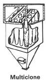
Multiple-cyclone separators consist of a number of small-diameter cyclones, operating in parallel and having a common gas inlet and outlet, as shown in the figure, and operate on the same principle as single cyclone separators—creating an outer downward vortex and an ascending inner vortex.

Multiple-cyclone separators remove more dust than single cyclone separators because the individual cyclones have a greater length and smaller diameter. The longer length provides longer residence time while the smaller diameter creates greater centrifugal force. These two factors result in better separation of dust particulates. The pressure drop of multiple-cyclone separators collectors is higher than that of single-cyclone separators, requiring more energy to clean the same amount of air. A single-chamber cyclone separator of the same volume is more economical, but doesn't remove as much dust.

Secondary-air-flow separators

This type of cyclone uses a secondary air flow, injected into the cyclone to accomplish several things. The secondary air flow increases the speed of the cyclonic action making the separator more efficient; it intercepts the particulate before it reaches the interior walls of the unit; and it forces the separated particulate toward the collection area. The secondary air flow protects the separator from particulate abrasion and allows the separator to be installed horizontally because gravity is not depended upon to move the separated particulate downward.

Cyclone theory

As the cyclone is essentially a two phase particle-fluid system, fluid mechanics and particle transport equations can be used to describe the behaviour of a cyclone. The air in a cyclone is initially introduced tangentially into the cyclone with an inlet velocity . Assuming that the particle is spherical, a simple analysis to calculate critical separation particle sizes can be established.

If one considers an isolated particle circling in the upper cylindrical component of the cyclone at a rotational radius of from the cyclone's central axis, the particle is therefore subjected to drag, centrifugal, and buoyant forces. Given that the fluid velocity is moving in a spiral the gas velocity can be broken into two component velocities: a tangential component, , and an outward radial velocity component . Assuming Stokes' law, the drag force in the outward radial direction that is opposing the outward velocity on any particle in the inlet stream is:

Using as the particle's density, the centrifugal component in the outward radial direction is:

The buoyant force component is in the inward radial direction. It is in the opposite direction to the particle's centrifugal force because it is on a volume of fluid that is missing compared to the surrounding fluid. Using for the density of the fluid, the buoyant force is:

In this case, is equal to the volume of the particle (as opposed to the velocity). Determining the outward radial motion of each particle is found by setting Newton's second law of motion equal to the sum of these forces:

To simplify this, we can assume the particle under consideration has reached "terminal velocity", i.e., that its acceleration is zero. This occurs when the radial velocity has caused enough drag force to counter the centrifugal and buoyancy forces. This simplification changes our equation to:

Which expands to:

Solving for we have

.

Notice that if the density of the fluid is greater than the density of the particle, the motion is (-), toward the center of rotation and if the particle is denser than the fluid, the motion is (+), away from the center. In most cases, this solution is used as guidance in designing a separator, while actual performance is evaluated and modified empirically.

In non-equilibrium conditions when radial acceleration is not zero, the general equation from above must be solved. Rearranging terms we obtain

Since is distance per time, this is a 2nd order differential equation of the form .

Experimentally it is found that the velocity component of rotational flow is proportional to , [4] therefore:

This means that the established feed velocity controls the vortex rate inside the cyclone, and the velocity at an arbitrary radius is therefore:

Subsequently, given a value for , possibly based upon the injection angle, and a cutoff radius, a characteristic particle filtering radius can be estimated, above which particles will be removed from the gas stream.

Alternative models

The above equations are limited in many regards. For example, the geometry of the separator is not considered, the particles are assumed to achieve a steady state and the effect of the vortex inversion at the base of the cyclone is also ignored, all behaviours which are unlikely to be achieved in a cyclone at real operating conditions.

More complete models exist, as many authors have studied the behaviour of cyclone separators., [5] simplified models allowing a quick calculation of the cyclone, with some limitations, have been developed for common applications in process industries. [6] Numerical modelling using computational fluid dynamics has also been used extensively in the study of cyclonic behaviour. [7] [8] [9] A major limitation of any fluid mechanics model for cyclone separators is the inability to predict the agglomeration of fine particles with larger particles, which has a great impact on cyclone collection efficiency. [10]

See also

Notes

  1. "Solid Gas separation methods - Industrial dust collectors - cyclone - scrubbers - filtration - PowderProcess.net".
  2. Jeven Oy. "How cyclone grease separators work". Archived from the original on 2017-04-21. Retrieved 2015-10-07.
  3. Martin Huard, Cedric Briens, Franco Berruti, Thierry Gauthier, 2010, "A Review of Rapid Gas-Solid Separation Techniques", IJCRE, 8, R1.
  4. Rhodes M. (1998). Introduction to particle technology. John Wiley and Sons. ISBN   978-0-471-98483-2.
  5. Smith, J. L. Jr. (1959). PhD thesis: Experimental and Analytical Study of the Vortex in the Cyclone Separator (Thesis). Massachusetts Institute of Technology. hdl:1721.1/11792.
  6. "Cyclone design - Step by step guide - Powderprocess.net" . Retrieved 26 March 2023.
  7. Martignoni, W. P.; Bernardo, S.; Quintani, C. L. (2007). "Evaluation of cyclone geometry and its influence on performance parameters by computational fluid dynamics (CFD)". Brazilian Journal of Chemical Engineering. 24: 83–94. doi: 10.1590/S0104-66322007000100008 .
  8. PhD Thesis: On the Potential of Large Eddy Simulation to Simulate Cyclone Separators (PDF). Archived from the original (PDF) on 2007-07-09. Retrieved 2009-06-20.
  9. PhD Thesis: Droplet collection in a scaled-up rotating separator (PDF).[ permanent dead link ]
  10. D. Benoni, C.L. Briens, T. Baron, E. Duchesne and T.M. Knowlton, 1994, "A procedure to determine particle agglomeration in a fluidized bed and its effect on entrainment", Powder Technology, 78, 33-42.

Related Research Articles

<span class="mw-page-title-main">Navier–Stokes equations</span> Equations describing the motion of viscous fluid substances

The Navier–Stokes equations are partial differential equations which describe the motion of viscous fluid substances. They were named after French engineer and physicist Claude-Louis Navier and the Irish physicist and mathematician George Gabriel Stokes. They were developed over several decades of progressively building the theories, from 1822 (Navier) to 1842–1850 (Stokes).

<span class="mw-page-title-main">Hydrostatic equilibrium</span> State of balance between external forces on a fluid and internal pressure gradient

In fluid mechanics, hydrostatic equilibrium is the condition of a fluid or plastic solid at rest, which occurs when external forces, such as gravity, are balanced by a pressure-gradient force. In the planetary physics of Earth, the pressure-gradient force prevents gravity from collapsing the planetary atmosphere into a thin, dense shell, whereas gravity prevents the pressure-gradient force from diffusing the atmosphere into outer space. In general, it is what causes objects in space to be spherical.

<span class="mw-page-title-main">Aerosol</span> Suspension of fine solid particles or liquid droplets in air or another gas

An aerosol is a suspension of fine solid particles or liquid droplets in air or another gas. Aerosols can be generated from natural or human causes. The term aerosol commonly refers to the mixture of particulates in air, and not to the particulate matter alone. Examples of natural aerosols are fog, mist or dust. Examples of human caused aerosols include particulate air pollutants, mist from the discharge at hydroelectric dams, irrigation mist, perfume from atomizers, smoke, dust, sprayed pesticides, and medical treatments for respiratory illnesses.

<span class="mw-page-title-main">Bernoulli's principle</span> Principle relating to fluid dynamics

Bernoulli's principle is a key concept in fluid dynamics that relates pressure, speed and height. Bernoulli's principle states that an increase in the speed of a parcel of fluid occurs simultaneously with a decrease in either the pressure or the height above a datum. The principle is named after the Swiss mathematician and physicist Daniel Bernoulli, who published it in his book Hydrodynamica in 1738. Although Bernoulli deduced that pressure decreases when the flow speed increases, it was Leonhard Euler in 1752 who derived Bernoulli's equation in its usual form.

The vorticity equation of fluid dynamics describes the evolution of the vorticity ω of a particle of a fluid as it moves with its flow; that is, the local rotation of the fluid. The governing equation is:

<span class="mw-page-title-main">Baroclinity</span> Measure of misalignment between the gradients of pressure and density in a fluid

In fluid dynamics, the baroclinity of a stratified fluid is a measure of how misaligned the gradient of pressure is from the gradient of density in a fluid. In meteorology a baroclinic flow is one in which the density depends on both temperature and pressure. A simpler case, barotropic flow, allows for density dependence only on pressure, so that the curl of the pressure-gradient force vanishes.

<span class="mw-page-title-main">Terminal velocity</span> Highest velocity attainable by a falling object

Terminal velocity is the maximum speed attainable by an object as it falls through a fluid. It is reached when the sum of the drag force (Fd) and the buoyancy is equal to the downward force of gravity (FG) acting on the object. Since the net force on the object is zero, the object has zero acceleration. For objects falling through air at normal pressure, the buoyant force is usually dismissed and not taken into account, as its effects are negligible.

<span class="mw-page-title-main">Settling</span> Process by which particulates move towards the bottom of a liquid and form a sediment

Settling is the process by which particulates move towards the bottom of a liquid and form a sediment. Particles that experience a force, either due to gravity or due to centrifugal motion will tend to move in a uniform manner in the direction exerted by that force. For gravity settling, this means that the particles will tend to fall to the bottom of the vessel, forming sludge or slurry at the vessel base. Settling is an important operation in many applications, such as mining, wastewater and drinking water treatment, biological science, space propellant reignition, and scooping.

In viscous fluid dynamics, the Archimedes number (Ar), is a dimensionless number used to determine the motion of fluids due to density differences, named after the ancient Greek scientist and mathematician Archimedes.

Quantum turbulence is the name given to the turbulent flow – the chaotic motion of a fluid at high flow rates – of quantum fluids, such as superfluids. The idea that a form of turbulence might be possible in a superfluid via the quantized vortex lines was first suggested by Richard Feynman. The dynamics of quantum fluids are governed by quantum mechanics, rather than classical physics which govern classical (ordinary) fluids. Some examples of quantum fluids include superfluid helium, Bose–Einstein condensates (BECs), polariton condensates, and nuclear pasta theorized to exist inside neutron stars. Quantum fluids exist at temperatures below the critical temperature at which Bose-Einstein condensation takes place.

In fluid dynamics, drag, sometimes referred to as fluid resistance, is a force acting opposite to the relative motion of any object, moving with respect to a surrounding fluid. This can exist between two fluid layers, two solid surfaces, or between a fluid and solid surface. Drag forces tend to decrease fluid velocity relative to the solid object in the fluid's path.

<span class="mw-page-title-main">Fluidized bed</span> Physical phenomenon

A fluidized bed is a physical phenomenon that occurs when a solid particulate substance is under the right conditions so that it behaves like a fluid. The usual way to achieve a fluidized bed is to pump pressurized fluid into the particles. The resulting medium then has many properties and characteristics of normal fluids, such as the ability to free-flow under gravity, or to be pumped using fluid technologies.

<span class="mw-page-title-main">Dust collector</span> Industrial machine

A dust collector is a system used to enhance the quality of air released from industrial and commercial processes by collecting dust and other impurities from air or gas. Designed to handle high-volume dust loads, a dust collector system consists of a blower, dust filter, a filter-cleaning system, and a dust receptacle or dust removal system. It is distinguished from air purifiers, which use disposable filters to remove dust.

<span class="mw-page-title-main">Eddy (fluid dynamics)</span> Swirling of a fluid and the reverse current created when the fluid is in a turbulent flow regime

In fluid dynamics, an eddy is the swirling of a fluid and the reverse current created when the fluid is in a turbulent flow regime. The moving fluid creates a space devoid of downstream-flowing fluid on the downstream side of the object. Fluid behind the obstacle flows into the void creating a swirl of fluid on each edge of the obstacle, followed by a short reverse flow of fluid behind the obstacle flowing upstream, toward the back of the obstacle. This phenomenon is naturally observed behind large emergent rocks in swift-flowing rivers.

<span class="mw-page-title-main">Lattice Boltzmann methods</span> Class of computational fluid dynamics methods

The lattice Boltzmann methods (LBM), originated from the lattice gas automata (LGA) method (Hardy-Pomeau-Pazzis and Frisch-Hasslacher-Pomeau models), is a class of computational fluid dynamics (CFD) methods for fluid simulation. Instead of solving the Navier–Stokes equations directly, a fluid density on a lattice is simulated with streaming and collision (relaxation) processes. The method is versatile as the model fluid can straightforwardly be made to mimic common fluid behaviour like vapour/liquid coexistence, and so fluid systems such as liquid droplets can be simulated. Also, fluids in complex environments such as porous media can be straightforwardly simulated, whereas with complex boundaries other CFD methods can be hard to work with.

The Kutta–Joukowski theorem is a fundamental theorem in aerodynamics used for the calculation of lift of an airfoil translating in a uniform fluid at a constant speed so large that the flow seen in the body-fixed frame is steady and unseparated. The theorem relates the lift generated by an airfoil to the speed of the airfoil through the fluid, the density of the fluid and the circulation around the airfoil. The circulation is defined as the line integral around a closed loop enclosing the airfoil of the component of the velocity of the fluid tangent to the loop. It is named after Martin Kutta and Nikolai Zhukovsky who first developed its key ideas in the early 20th century. Kutta–Joukowski theorem is an inviscid theory, but it is a good approximation for real viscous flow in typical aerodynamic applications.

<span class="mw-page-title-main">Reynolds number</span> Ratio of inertial to viscous forces acting on a liquid

In fluid dynamics, the Reynolds number is a dimensionless quantity that helps predict fluid flow patterns in different situations by measuring the ratio between inertial and viscous forces. At low Reynolds numbers, flows tend to be dominated by laminar (sheet-like) flow, while at high Reynolds numbers, flows tend to be turbulent. The turbulence results from differences in the fluid's speed and direction, which may sometimes intersect or even move counter to the overall direction of the flow. These eddy currents begin to churn the flow, using up energy in the process, which for liquids increases the chances of cavitation.

The multiphase particle-in-cell method (MP-PIC) is a numerical method for modeling particle-fluid and particle-particle interactions in a computational fluid dynamics (CFD) calculation. The MP-PIC method achieves greater stability than its particle-in-cell predecessor by simultaneously treating the solid particles as computational particles and as a continuum. In the MP-PIC approach, the particle properties are mapped from the Lagrangian coordinates to an Eulerian grid through the use of interpolation functions. After evaluation of the continuum derivative terms, the particle properties are mapped back to the individual particles. This method has proven to be stable in dense particle flows, computationally efficient, and physically accurate. This has allowed the MP-PIC method to be used as particle-flow solver for the simulation of industrial-scale chemical processes involving particle-fluid flows.

In fluid dynamics, the Basset–Boussinesq–Oseen equation describes the motion of – and forces on – a small particle in unsteady flow at low Reynolds numbers. The equation is named after Joseph Valentin Boussinesq, Alfred Barnard Basset and Carl Wilhelm Oseen.

<span class="mw-page-title-main">Jet mill</span> Pneumatic powered mill

A jet mill grinds materials by using a high speed jet of compressed air or inert gas to impact particles into each other. Jet mills can be designed to output particles below a certain size while continuing to mill particles above that size, resulting in a narrow size distribution of the resulting product. Particles leaving the mill can be separated from the gas stream by cyclonic separation.

References