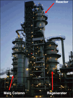
A typical fluid catalytic cracking unit in a petroleum refinery.
Fluid catalytic cracking (FCC) is the conversion process used in petroleum refineries to convert the high-boiling point, high-molecular weight hydrocarbon fractions of petroleum (crude oils) into gasoline, alkene gases, and other petroleum products.[1][2][3] The cracking of petroleum hydrocarbons was originally done by thermal cracking, now virtually replaced by catalytic cracking, which yields greater volumes of high octane rating gasoline; and produces by-product gases, with more carbon-carbon double bonds (i.e. alkenes), that are of greater economic value than the gases produced by thermal cracking.
The feedstock to the FCC conversion process usually is heavy gas oil (HGO), which is that portion of the petroleum (crude oil) that has an initial boiling-point temperature of 340°C (644°F) or higher, at atmospheric pressure, and that has an average molecular weight that ranges from about 200 to 600 or higher; heavy gas oil also is known as "heavy vacuum gas oil" (HVGO). In the fluid catalytic cracking process, the HGO feedstock is heated to a high temperature and to a moderate pressure, and then is placed in contact with a hot, powdered catalyst, which breaks the long-chain molecules of the high-boiling-point hydrocarbon liquids into short-chain molecules, which then are collected as a vapor.
Economics
Oil refineries use fluid catalytic cracking to correct the imbalance between the market demand for gasoline and the excess of heavy, high boiling range products resulting from the distillation of crude oil.
As of 2006, FCC units were in operation at 400 petroleum refineries worldwide, and about one-third of the crude oil refined in those refineries is processed in an FCC to produce high-octane gasoline and fuel oils.[2][4] During 2007, the FCC units in the United States processed a total of 5,300,000 barrels (840,000m3) of feedstock per day,[5] and FCC units worldwide processed about twice that amount.
FCC units are less common in Europe, the Middle East and Africa (EMEA) because those regions have high demand for diesel and kerosene, which can be satisfied with hydrocracking. In the US, fluid catalytic cracking is more common because the demand for gasoline is higher.
Flow diagram and process description
The modern FCC units are all continuous processes which operate 24 hours a day for as long as 3 to 5 years between scheduled shutdowns for routine maintenance.[6][7]
Several proprietary designs have been developed for modern FCC units. There are two configurations for an FCC unit: the "stacked" type where the reactor and the catalyst regenerator are contained in two separate vessels, with the reactor above the regenerator, with a skirt between these vessels allowing the regenerator off-gas piping to connect to the top of the regenerator vessel, and the "side-by-side" type where the reactor and catalyst regenerator are in two separate vessels. The stacked configuration occupies less physical space of the refinery area. These are the major FCC designers and licensors:[1][3][4][8]
The reactor and regenerator are the heart of the FCC unit. The schematic flow diagram of a typical modern FCC unit in Figure 1 below is based upon the "side-by-side" configuration. The preheated high-boiling petroleum feedstock (at about 315 to 430°C) is combined with recycle slurry oil from the bottom of the distillation column and injected into the catalyst riser where it vaporises. In the riser, long-chain hydrocarbons cracked into smaller molecules upon contact with the hot powdered catalyst in 2–4 seconds. The hydrocarbon vapours "fluidize" the powdered catalyst and the mixture of hydrocarbon vapors and catalyst flows upward to enter the reactor at a temperature of about 535°C and a pressure of about 1.72bar.
The reactor vessel contains the catalyst in which the cracked product vapors are formed by flowing through a set of two-stage cyclones. The spent catalyst flows downward through a steam stripping section to remove any hydrocarbon vapors before the spent catalyst returns to the catalyst regenerator. The flow of spent catalyst to the regenerator is regulated by a slide valve in the spent catalyst line. The inventory of catalyst in an FCC unit is about 150 tons.[9]
Cracking deposits carbonaceous material (referred to as catalyst coke) on the catalyst, which lowers its activity. The catalyst is regenerated by burning off the deposited coke with air blown into the regenerator. The regenerator operates at a temperature of about 715°C and a pressure of about 2.41bar, hence the regenerator operates at about 0.7bar higher pressure than the reactor. The combustion of the coke is exothermic. This heat is partially absorbed by the regenerated catalyst and provides the heat required for the vaporization of the hydrocarbon feedstock and the endothermic cracking reactions that occur in the catalyst riser. For that reason, FCC units are often referred to as being 'heat balanced'.
The hot catalyst (at about 715°C) leaving the regenerator flows into a catalyst withdrawal well where any entrained combustion flue gases are allowed to escape and flow back into the upper part to the regenerator. The flow of regenerated catalyst to the feedstock injection point below the catalyst riser is regulated by a slide valve in the regenerated catalyst line. The hot flue gas exits the regenerator after passing through multiple sets of two-stage cyclones that remove entrained catalyst from the flue gas.
The amount of catalyst circulating between the regenerator and the reactor amounts to about 5kg per kg of feedstock, which is equivalent to about 4.66kg per litre of feedstock.[1][10] Thus, an FCC unit processing 75,000 barrels per day (11,900m3/d) will circulate about 55,900tonnes per day of catalyst.[7][6]
Figure 1: A schematic flow diagram of a FCC unit as used in petroleum refineries
Main column
The reaction product vapors (at 535°C and a pressure of1.72 bar) flow from the top of the reactor to the bottom section of the main column (commonly referred to as the main fractionator where feed splitting takes place) where they are distilled into the FCC end products of cracked petroleum naphtha, fuel oil, and offgas. After further processing for removal of sulfur compounds, the cracked naphtha becomes a high-octane component of the refinery's blended gasolines.
The main fractionator offgas is sent to what is called a gas recovery unit where it is separated into butanes and butylenes, propane and propylene, and lower molecular weight gases (hydrogen, methane, ethylene and ethane). Some FCC gas recovery units may also separate out some of the ethane and ethylene.
Although the schematic flow diagram above depicts the main fractionator as having only one sidecut stripper and one fuel oil product, many FCC main fractionators have two sidecut strippers and produce a light fuel oil and a heavy fuel oil. Likewise, many FCC main fractionators produce a light cracked naphtha and a heavy cracked naphtha. The terminology light and heavy in this context refers to the product boiling ranges, with light products having a lower boiling range than heavy products.
The bottom product oil from the main fractionator contains residual catalyst particles which were not completely removed by the cyclones in the top of the reactor. For that reason, the bottom product oil is referred to as a slurry oil. Part of that slurry oil is recycled back into the main fractionator above the entry point of the hot reaction product vapors so as to cool and partially condense the reaction product vapors as they enter the main fractionator. The remainder of the slurry oil is pumped through a slurry settler. The bottom oil from the slurry settler contains most of the slurry oil catalyst particles and is recycled back into the catalyst riser by combining it with the FCC feedstock oil. The clarified slurry oil or decant oil is withdrawn from the top of slurry settler for use elsewhere in the refinery, as a heavy fuel oil blending component, or as carbon black feedstock.
Regenerator flue gas
Depending on the choice of FCC design, the combustion in the regenerator of the coke on the spent catalyst may or may not be complete combustion to carbon dioxide CO2. The combustion air flow is controlled so as to provide the desired ratio of carbon monoxide (CO) to carbon dioxide for each specific FCC design.[1][4]
In the design shown in Figure 1, the coke has only been partially combusted to CO2. The combustion flue gas (containing CO and CO2) at 715°C and at a pressure of 2.41bar is routed through a secondary catalyst separator containing swirl tubes designed to remove 70 to 90 percent of the particulates in the flue gas leaving the regenerator.[11] This is required to prevent erosion damage to the blades in the turbo-expander that the flue gas is next routed through.
The expansion of flue gas through a turbo-expander provides sufficient power to drive the regenerator's combustion air compressor. The electrical motor–generator can consume or produce electrical power. If the expansion of the flue gas does not provide enough power to drive the air compressor, the electric motor–generator provides the needed additional power. If the flue gas expansion provides more power than needed to drive the air compressor, then the electric motor–generator converts the excess power into electric power and exports it to the refinery's electrical system.[3]
The expanded flue gas is then routed through a steam-generating boiler (referred to as a CO boiler) where the carbon monoxide in the flue gas is burned as fuel to provide steam for use in the refinery as well as to comply with any applicable environmental regulatory limits on carbon monoxide emissions.[3]
The flue gas is finally processed through an electrostatic precipitator (ESP) to remove residual particulate matter to comply with any applicable environmental regulations regarding particulate emissions. The ESP removes particulates in the size range of 2 to 20μm from the flue gas.[3] Particulate filter systems, known as Fourth Stage Separators (FSS) are sometimes required to meet particulate emission limits. These can replace the ESP when particulate emissions are the only concern.
The steam turbine in the flue gas processing system (shown in the above diagram) is used to drive the regenerator's combustion air compressor during start-ups of the FCC unit until there is sufficient combustion flue gas to take over that task.
Mechanism and products of catalytic cracking
Figure 2: Diagrammatic example of the catalytic cracking of petroleum hydrocarbons
The fluid catalytic cracking process breaks large hydrocarbons by their conversion to carbocations, which undergo myriad rearrangements.[12]
Figure 2 is a very simplified schematic diagram that exemplifies how the process breaks high boiling, straight-chain alkane (paraffin) hydrocarbons into smaller straight-chain alkanes as well as branched-chain alkanes, branched alkenes (olefins) and cycloalkanes (naphthenes). The breaking of the large hydrocarbon molecules into smaller molecules is more technically referred to by organic chemists as scission of the carbon-to-carbon bonds.
As depicted in Figure 2, some of the smaller alkanes are then broken and converted into even smaller alkenes and branched alkenes such as the gases ethylene, propylene, butylenes, and isobutylenes. Those olefinic gases are valuable for use as petrochemical feedstocks. The propylene, butylene and isobutylene are also valuable feedstocks for certain petroleum refining processes that convert them into high-octane gasoline blending components.
As also depicted in Figure 2, the cycloalkanes (naphthenes) formed by the initial breakup of the large molecules are further converted to aromatics such as benzene, toluene, and xylenes, which boil in the gasoline boiling range and have much higher octane ratings than alkanes.
FCC units continuously withdraw and replace some of the catalyst in order to maintain a steady level of activity. Modern FCC catalysts are fine powders with a bulk density of 0.80 to 0.96g/cm3 and having a particle size distribution ranging from 10 to 150μm and an average particle size of 60 to 100μm.[13][14] The design and operation of an FCC unit is largely dependent upon the chemical and physical properties of the catalyst. The desirable properties of an FCC catalyst are:
Good stability to high temperature and to steam
High activity
Large pore sizes
Good resistance to attrition
Low coke production
Structure of aluminosilicate cage in faujasite. Vertices are occupied by aluminium or silicon, the connecting struts are occupied by oxide (O ) or hydroxide (OH ) centers. Special modifications of faujesite are strong solid acids, which at high temperatures induce the rearrangements of C-C bonds that occur in FCC units.
A modern FCC catalyst has four major components: crystalline zeolite, matrix, binder, and filler. Zeolite is the active component and can comprise from about 15% to 50%, by weight, of the catalyst. Faujasite (aka Type Y) is the zeolite used in FCC units.[6] The zeolites are strong solid acids (equivalent to 90% sulfuric acid).[citation needed] The alumina matrix component of an FCC catalyst also contributes to catalytic activity sites. The binder and filler components provide the physical strength and integrity of the catalyst. The binder is usually silica sol and the filler is usually a clay (kaolin).[13][14] The predominant suppliers of FCC catalysts worldwide are Albemarle Corporation, W.R. Grace Company, and BASF Catalysts (formerly Engelhard).
History
The first commercial use of catalytic cracking occurred in 1915 when Almer M. McAfee of Gulf Refining Company developed a batch process using aluminium chloride (a Friedel–Crafts catalyst known since 1877) to catalytically crack heavy petroleum oils. However, the prohibitive cost of the catalyst prevented the widespread use of McAfee's process at that time.[2][15]
In 1922, a French mechanical engineer named Eugene Jules Houdry and a French pharmacist named E. A. Prudhomme set up a laboratory near Paris to develop a catalytic process for converting lignite coal to gasoline. Supported by the French government, they built a small demonstration plant in 1929 that processed about 60 tons per day of lignite coal. The results indicated that the process was not economically viable and it was subsequently shut down.[16][17][18]
Houdry had found that Fuller's earth, a clay mineral containing aluminosilicates, could convert oil derived from the lignite to gasoline. He then began to study the catalysis of petroleum oils and had some success in converting vaporized petroleum oil to gasoline. In 1930, the Vacuum Oil Company invited him to come to the United States and he moved his laboratory to Paulsboro, New Jersey.
In 1931, the Vacuum Oil Company merged with Standard Oil of New York (Socony) to form the Socony-Vacuum Oil Company. In 1933, a small Houdry unit processed 200 barrels per day (32m3/d) of petroleum oil. Because of the economic depression of the early 1930s, Socony-Vacuum was no longer able to support Houdry's work and gave him permission to seek help elsewhere.
In 1933, Houdry and Socony-Vacuum joined with Sun Oil Company in developing the Houdry process. Three years later, in 1936, Socony-Vacuum converted an older thermal cracking unit in their Paulsboro refinery in New Jersey to a small demonstration unit using the Houdry process to catalytically crack 2,000 barrels per day (320m3/d) of petroleum oil.
In 1937, Sun Oil began operation of a new Houdry unit processing 12,000 barrels per day (1,900m3/d) at their Marcus Hook refinery in Pennsylvania. The Houdry process at that time used reactors with a fixed bed of catalyst and was a semi-batch operation involving multiple reactors with some of the reactors in operation while other reactors were in various stages of regenerating the catalyst. Motor-driven valves were used to switch the reactors between online operation and offline regeneration and a cycle timer managed the switching. Almost 50 percent of the cracked product was gasoline as compared with about 25 percent from the thermal cracking processes.[16][17][18]
By 1938, when the Houdry process was publicly announced, Socony-Vacuum had eight additional units under construction. Licensing the process to other companies also began and by 1940 there were 14 Houdry units in operation processing 140,000 barrels per day (22,000m3/d).
The next major step was to develop a continuous process rather than the semi-batch Houdry process. That step was implemented by advent of the moving-bed process known as the Thermofor Catalytic Cracking (TCC) process which used a bucket conveyor-elevator to move the catalyst from the regeneration kiln to the separate reactor section. A small semi-commercial demonstration TCC unit was built in Socony-Vacuum's Paulsboro refinery in 1941 and operated successfully, producing 500 barrels per day (79m3/d). Then a full-scale commercial TCC unit processing 10,000 barrels per day (1,600m3/d) began operation in 1943 at the Beaumont, Texas refinery of Magnolia Oil Company, an affiliate of Socony-Vacuum. By the end of World War II in 1945, the processing capacity of the TCC units in operation was about 300,000 barrels per day (48,000m3/d).
It is said that the Houdry and TCC units were a major factor in the winning of World War II by supplying the high-octane gasoline needed by the air forces of Great Britain and the United States for the more efficient higher compression ratio engines of the Spitfire and the Mustang.[16][17][18] Supplies of American aviation gas also negated the deficit of high-octane gasoline for the Red Army Air Force.
In the years immediately after World War II, the Houdriflow process and the air-lift TCC process were developed as improved variations on the moving-bed theme. Just like Houdry's fixed-bed reactors, the moving-bed designs were prime examples of good engineering by developing a method of continuously moving the catalyst between the reactor and regeneration sections. The first air-lift TCC unit began operation in October 1950 at the Beaumont, Texas refinery.
This fluid catalytic cracking process had first been investigated in the 1920s by Standard Oil of New Jersey, but research on it was abandoned during the economic depression years of 1929 to 1939. In 1938, when the success of Houdry's process had become apparent, Standard Oil of New Jersey resumed the project, hopefully in competition with Houdry, as part of a consortium of that include five oil companies (Standard Oil of New Jersey, Standard Oil of Indiana, Anglo-Iranian Oil, Texas Oil and Royal Dutch Shell), two engineering-construction companies (M. W. Kellogg Limited and Universal Oil Products) and a German chemical company (I.G. Farben). The consortium was called Catalytic Research Associates (CRA) and its purpose was to develop a catalytic cracking process which would not impinge on Houdry's patents.[16][17][18]
Chemical engineering professors Warren K. Lewis and Edwin R. Gilliland of the Massachusetts Institute of Technology (MIT) suggested to the CRA researchers that a low velocity gas flow through a powder might "lift" it enough to cause it to flow in a manner similar to a liquid. Focused on that idea of a fluidized catalyst, researchers Donald Campbell, Homer Martin, Eger Murphree and Charles Tyson of the Standard Oil of New Jersey (now Exxon-Mobil Company) developed the first fluidized catalytic cracking unit. Their U.S. Patent No. 2,451,804, A Method of and Apparatus for Contacting Solids and Gases, describes their milestone invention. Based on their work, M. W. Kellogg Company constructed a large pilot plant in the Baton Rouge, Louisiana refinery of the Standard Oil of New Jersey. The pilot plant began operation in May 1940.
Based on the success of the pilot plant, the first commercial fluid catalytic cracking plant (known as the Model I FCC) began processing 13,000 barrels per day (2,100m3/d) of petroleum oil in the Baton Rouge refinery on May 25, 1942, just four years after the CRA consortium was formed and in the midst of World War II. A little more than a month later, in July 1942, it was processing 17,000 barrels per day (2,700m3/d). In 1963, that first Model I FCC unit was shut down after 21 years of operation and subsequently dismantled.[16][17][18][19]
In the many decades since the Model I FCC unit began operation, the fixed bed Houdry units have all been shut down as have most of the moving bed units (such as the TCC units) while hundreds of FCC units have been built. During those decades, many improved FCC designs have evolved and cracking catalysts have been greatly improved, but the modern FCC units are essentially the same as that first Model I FCC unit.
Typical Yields for a Modern FCC
All table yields taken from the Fluid Catalytic Cracking Handbook[20]
1 2 3 4 David S.J. Jones and Peter P. Pujado (Editors) (2006). Handbook of Petroleum Processing (Firsted.). Springer. ISBN1-4020-2819-9.{{cite book}}: |author= has generic name (help)
↑ Alex C. Hoffmann; Lewis E. Stein (2002). Gas Cyclones and Swirl Tubes:Principles, Design and Operation (1sted.). Springer. ISBN3-540-43326-0.
↑ Rahimi, Nazi; Karimzadeh, Ramin (2011). "Catalytic cracking of hydrocarbons over modified ZSM-5 zeolites to produce light olefins: A review". Applied Catalysis A: General. 398 (1–2): 1–17. Bibcode:2011AppCA.398....1R. doi:10.1016/j.apcata.2011.03.009.
1 2 Jessica Elzea Kogel, Nikhil C. Trivedi, James M. Barber and Stanley T. Krukowsk (Editors) (2006). Industrial Minerals & Rocks: Commodities, Markets and Uses (Seventhed.). Society of Mining, Metallurgy and Exploration. ISBN0-87335-233-5.{{cite book}}: |author= has generic name (help)CS1 maint: multiple names: authors list (link)
1 2 Wen-Ching Yang (2003). Handbook of Fluidization and Fluid Particle Systems. CRC Press. ISBN0-8247-0259-X.
This page is based on this Wikipedia article Text is available under the CC BY-SA 4.0 license; additional terms may apply. Images, videos and audio are available under their respective licenses.