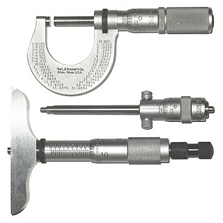
A micrometer, sometimes known as a micrometer screw gauge, is a device incorporating a calibrated screw widely used for accurate measurement of components in mechanical engineering and machining as well as most mechanical trades, along with other metrological instruments such as dial, vernier, and digital calipers. Micrometers are usually, but not always, in the form of calipers. The spindle is a very accurately machined screw and the object to be measured is placed between the spindle and the anvil. The spindle is moved by turning the ratchet knob or thimble until the object to be measured is lightly touched by both the spindle and the anvil.
In petroleum exploration and development, formation evaluation is used to determine the ability of a borehole to produce petroleum. Essentially, it is the process of "recognizing a commercial well when you drill one".

In materials science, fatigue is the initiation and propagation of cracks in a material due to cyclic loading. Once a fatigue crack has initiated, it grows a small amount with each loading cycle, typically producing striations on some parts of the fracture surface. The crack will continue to grow until it reaches a critical size, which occurs when the stress intensity factor of the crack exceeds the fracture toughness of the material, producing rapid propagation and typically complete fracture of the structure.

Drilling is a cutting process that uses a drill bit to cut a hole of circular cross-section in solid materials. The drill bit is usually a rotary cutting tool, often multi-point. The bit is pressed against the work-piece and rotated at rates from hundreds to thousands of revolutions per minute. This forces the cutting edge against the work-piece, cutting off chips (swarf) from the hole as it is drilled.

A bolted joint is one of the most common elements in construction and machine design. It consist of a male threaded fastener that captures and joins other parts, secured with a matching female screw thread. There are two main types of bolted joint designs: tension joints and shear joints.

Autofrettage is a work hardening process in which a pressure vessel is subjected to enormous pressure, causing internal portions of the part to yield plastically, resulting in internal compressive residual stresses once the pressure is released. The goal of autofrettage is to increase the pressure carrying capacity of the final product. Inducing residual compressive stresses into materials can also increase their resistance to stress corrosion cracking; that is, non-mechanically-assisted cracking that occurs when a material is placed in a corrosive environment in the presence of tensile stress. The technique is commonly used in manufacture of high-pressure pump cylinders, warship and gun barrels, and fuel injection systems for diesel engines. Due to work hardening process it also enhances wear life of the barrel marginally. While autofrettage will induce some work hardening, that is not the primary mechanism of strengthening.
Well logging, also known as borehole logging is the practice of making a detailed record of the geologic formations penetrated by a borehole. The log may be based either on visual inspection of samples brought to the surface or on physical measurements made by instruments lowered into the hole. Some types of geophysical well logs can be done during any phase of a well's history: drilling, completing, producing, or abandoning. Well logging is performed in boreholes drilled for the oil and gas, groundwater, mineral and geothermal exploration, as well as part of environmental and geotechnical studies.

In materials science and solid mechanics, residual stresses are stresses that remain in a solid material after the original cause of the stresses has been removed. Residual stress may be desirable or undesirable. For example, laser peening imparts deep beneficial compressive residual stresses into metal components such as turbine engine fan blades, and it is used in toughened glass to allow for large, thin, crack- and scratch-resistant glass displays on smartphones. However, unintended residual stress in a designed structure may cause it to fail prematurely.
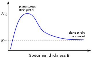
In materials science, fracture toughness is the critical stress intensity factor of a sharp crack where propagation of the crack suddenly becomes rapid and unlimited. A component's thickness affects the constraint conditions at the tip of a crack with thin components having plane stress conditions and thick components having plane strain conditions. Plane strain conditions give the lowest fracture toughness value which is a material property. The critical value of stress intensity factor in mode I loading measured under plane strain conditions is known as the plane strain fracture toughness, denoted . When a test fails to meet the thickness and other test requirements that are in place to ensure plane strain conditions, the fracture toughness value produced is given the designation . Fracture toughness is a quantitative way of expressing a material's resistance to crack propagation and standard values for a given material are generally available.
Nanoindentation, also called instrumented indentation testing, is a variety of indentation hardness tests applied to small volumes. Indentation is perhaps the most commonly applied means of testing the mechanical properties of materials. The nanoindentation technique was developed in the mid-1970s to measure the hardness of small volumes of material.
The original depth recorded while drilling an oil or gas well is known as the driller's depth.

Deep drawing is a sheet metal forming process in which a sheet metal blank is radially drawn into a forming die by the mechanical action of a punch. It is thus a shape transformation process with material retention. The process is considered "deep" drawing when the depth of the drawn part exceeds its diameter. This is achieved by redrawing the part through a series of dies. The flange region experiences a radial drawing stress and a tangential compressive stress due to the material retention property. These compressive stresses result in flange wrinkles. Wrinkles can be prevented by using a blank holder, the function of which is to facilitate controlled material flow into the die radius.
A test method is a method for a test in science or engineering, such as a physical test, chemical test, or statistical test. It is a definitive procedure that produces a test result. In order to ensure accurate and relevant test results, a test method should be "explicit, unambiguous, and experimentally feasible.", as well as effective and reproducible.
The impulse excitation technique (IET) is a non-destructive material characterization technique to determine the elastic properties and internal friction of a material of interest. It measures the resonant frequencies in order to calculate the Young's modulus, shear modulus, Poisson's ratio and internal friction of predefined shapes like rectangular bars, cylindrical rods and disc shaped samples. The measurements can be performed at room temperature or at elevated temperatures under different atmospheres.
Rutherford backscattering spectrometry (RBS) is an analytical technique used in materials science. Sometimes referred to as high-energy ion scattering (HEIS) spectrometry, RBS is used to determine the structure and composition of materials by measuring the backscattering of a beam of high energy ions impinging on a sample.

Burnishing is the plastic deformation of a surface due to sliding contact with another object. It smooths the surface and makes it shinier. Burnishing may occur on any sliding surface if the contact stress locally exceeds the yield strength of the material. The phenomenon can occur both unintentionally as a failure mode, and intentionally as part of a manufacturing process. It is a squeezing operation under cold working.

Precision glass moulding is a replicative process that allows the production of high precision optical components from glass without grinding and polishing. The process is also known as ultra-precision glass pressing. It is used to manufacture precision glass lenses for consumer products such as digital cameras, and high-end products like medical systems. The main advantage over mechanical lens production is that complex lens geometries such as aspheres can be produced cost-efficiently.
Increased intracranial pressure (ICP) is one of the major causes of secondary brain ischemia that accompanies a variety of pathological conditions, most notably traumatic brain injury (TBI), strokes, and intracranial hemorrhages. It can cause complications such as vision impairment due to intracranial pressure (VIIP), permanent neurological problems, reversible neurological problems, seizures, stroke, and death. However, aside from a few Level I trauma centers, ICP monitoring is rarely a part of the clinical management of patients with these conditions. The infrequency of ICP can be attributed to the invasive nature of the standard monitoring methods. Additional risks presented to patients can include high costs associated with an ICP sensor's implantation procedure, and the limited access to trained personnel, e.g. a neurosurgeon. Alternative, non-invasive measurement of intracranial pressure, non-invasive methods for estimating ICP have, as a result, been sought.
Reversibly assembled cellular composite materials (RCCM) are three-dimensional lattices of modular structures that can be partially disassembled to enable repairs or other modifications. Each cell incorporates structural material and a reversible interlock, allowing lattices of arbitrary size and shape. RCCM display three-dimensional symmetry derived from the geometry as linked.

The hole drilling method is a method for measuring residual stresses, in a material. Residual stress occurs in a material in the absence of external loads. Residual stress interacts with the applied loading on the material to affect the overall strength, fatigue, and corrosion performance of the material. Residual stresses are measured through experiments. The hole drilling method is one of the most used methods for residual stress measurement.

