Related Research Articles

In telecommunications, RS-232 or Recommended Standard 232 is a standard originally introduced in 1960 for serial communication transmission of data. It formally defines signals connecting between a DTE such as a computer terminal or PC, and a DCE, such as a modem. The standard defines the electrical characteristics and timing of signals, the meaning of signals, and the physical size and pinout of connectors. The current version of the standard is TIA-232-F Interface Between Data Terminal Equipment and Data Circuit-Terminating Equipment Employing Serial Binary Data Interchange, issued in 1997.
In telecommunications and professional audio, a balanced line or balanced signal pair is an electrical circuit consisting of two conductors of the same type, both of which have equal impedances along their lengths, to ground, and to other circuits. The primary advantage of the balanced line format is good rejection of common-mode noise and interference when fed to a differential device such as a transformer or differential amplifier.
Capacitive coupling is the transfer of energy within an electrical network or between distant networks by means of displacement current between circuit(s) nodes, induced by the electric field. This coupling can have an intentional or accidental effect.

In electronics, a comparator is a device that compares two voltages or currents and outputs a digital signal indicating which is larger. It has two analog input terminals and and one binary digital output . The output is ideally
Transistor–transistor logic (TTL) is a logic family built from bipolar junction transistors. Its name signifies that transistors perform both the logic function and the amplifying function, as opposed to earlier resistor–transistor logic (RTL) and diode–transistor logic (DTL).
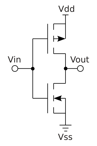
Complementary metal–oxide–semiconductor is a type of metal–oxide–semiconductor field-effect transistor (MOSFET) fabrication process that uses complementary and symmetrical pairs of p-type and n-type MOSFETs for logic functions. CMOS technology is used for constructing integrated circuit (IC) chips, including microprocessors, microcontrollers, memory chips, and other digital logic circuits. CMOS technology is also used for analog circuits such as image sensors, data converters, RF circuits, and highly integrated transceivers for many types of communication.

Low-voltage differential signaling (LVDS), also known as TIA/EIA-644, is a technical standard that specifies electrical characteristics of a differential, serial signaling standard. LVDS operates at low power and can run at very high speeds using inexpensive twisted-pair copper cables. LVDS is a physical layer specification only; many data communication standards and applications use it and add a data link layer as defined in the OSI model on top of it.
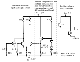
In electronics, emitter-coupled logic (ECL) is a high-speed integrated circuit bipolar transistor logic family. ECL uses an overdriven bipolar junction transistor (BJT) differential amplifier with single-ended input and limited emitter current to avoid the saturated region of operation and the resulting slow turn-off behavior. As the current is steered between two legs of an emitter-coupled pair, ECL is sometimes called current-steering logic (CSL), current-mode logic (CML) or current-switch emitter-follower (CSEF) logic.

RS-422, also known as TIA/EIA-422, is a technical standard originated by the Electronic Industries Alliance, first issued in 1975, that specifies electrical characteristics of a digital signaling circuit. It was meant to be the foundation of a suite of standards that would replace the older RS-232C standard with standards that offered much higher speed, better immunity from noise, and longer cable lengths. RS-422 systems can transmit data at rates as high as 10 Mbit/s, or may be sent on cables as long as 1,200 meters (3,900 ft) at lower rates. It is closely related to RS-423, which uses the same signaling systems but on a different wiring arrangement.
In an electrical system, a ground loop or earth loop occurs when two points of a circuit are intended to have the same ground reference potential but instead have a different potential between them. This is typically caused when enough current is flowing in the connection between the two ground points to produce a voltage drop and cause the two points to be at different potentials. Current may be produced in a ground loop by electromagnetic induction.
In computer engineering, a logic family is one of two related concepts:
RS-485, also known as TIA-485(-A) or EIA-485, is a standard, originally introduced in 1983, defining the electrical characteristics of drivers and receivers for use in serial communications systems. Electrical signaling is balanced, and multipoint systems are supported. The standard is jointly published by the Telecommunications Industry Association and Electronic Industries Alliance (TIA/EIA). Digital communications networks implementing the standard can be used effectively over long distances and in electrically noisy environments. Multiple receivers may be connected to such a network in a linear, multidrop bus. These characteristics make RS-485 useful in industrial control systems and similar applications.

Differential signalling is a method for electrically transmitting information using two complementary signals. The technique sends the same electrical signal as a differential pair of signals, each in its own conductor. The pair of conductors can be wires in a twisted-pair or ribbon cable or traces on a printed circuit board.
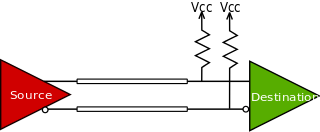
Current mode logic (CML), or source-coupled logic (SCL), is a digital design style used both for logic gates and for board-level digital signaling of digital data.
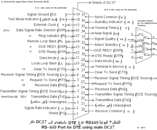
The RS-449 specification, also known as EIA-449 or TIA-449, defines the functional and mechanical characteristics of the interface between data terminal equipment, typically a computer, and data communications equipment, typically a modem or terminal server. The full title of the standard is EIA-449 General Purpose 37-Position and 9-Position Interface for Data Terminal Equipment and Data Circuit-Terminating Equipment Employing Serial Binary Data Interchange.
Single-ended signaling is the simplest and most commonly used method of transmitting electrical signals over wires. One wire carries a varying voltage that represents the signal, while the other wire is connected to a reference voltage, usually ground. The main alternative to single-ended signaling is called differential signaling where the two conductors carry signals equal in magnitude but of opposite electric polarity.

Integrated injection logic (IIL, I2L, or I2L) is a class of digital circuits built with multiple collector bipolar junction transistors (BJT). When introduced it had speed comparable to TTL yet was almost as low power as CMOS, making it ideal for use in VLSI (and larger) integrated circuits. The gates can be made smaller with this logic family than with CMOS because complementary transistors are not needed. Although the logic voltage levels are very close (High: 0.7V, Low: 0.2V), I2L has high noise immunity because it operates by current instead of voltage. I2L was developed in 1971 by Siegfried K. Wiedmann and Horst H. Berger who originally called it merged-transistor logic (MTL). A disadvantage of this logic family is that the gates draw power when not switching unlike with CMOS.
In digital circuits, a logic level is one of a finite number of states that a digital signal can inhabit. Logic levels are usually represented by the voltage difference between the signal and ground, although other standards exist. The range of voltage levels that represent each state depends on the logic family being used. A logic-level shifter can be used to allow compatibility between different circuits.

The MAX232 is an integrated circuit by Maxim Integrated Products, now a subsidiary of Analog Devices, that converts signals from a TIA-232 (RS-232) serial port to signals suitable for use in TTL-compatible digital logic circuits. The MAX232 is a dual transmitter / dual receiver that typically is used to convert the RX, TX, CTS, RTS signals.
In digital electronics, a level shifter, also called level converter or logic level shifter, or voltage level translator, is a circuit used to translate signals from one logic level or voltage domain to another, allowing compatibility between integrated circuits with different voltage requirements, such as TTL and CMOS. Modern systems use level shifters to bridge domains between processors, logic, sensors, and other circuits. In recent years, the three most common logic levels have been 1.8V, 3.3V, and 5V, though levels above and below these voltages are also used.
References
- ↑ Paul D. Biernacki; Michael Y. Frankel; Michael E. Gingerich; Paul J. Matthews (1999). "A High-Speed Mixed Digital-to-Analog Circuit Board for Accurate Control of Wavelength Tunable Lasers for Fiber-Optic Communications". Journal of Lightwave Technology. 17 (7): 1222. Bibcode:1999JLwT...17.1222B. doi:10.1109/50.774260.
- ↑ "B&B Electronics - Polarities for Differential Pair Signals (RS-422 and RS-485)". www.bb-elec.com.
- ↑ Buchanan, James Edgar (1996). Signal and Power Integrity in Digital Systems: TTL, CMOS, and BiCMOS. McGraw-Hill. p. 200. ISBN 0070087342.
- ↑ Louis Columbus (2000). Exploring the World of SCSI. LWC Research. p. 20. ISBN 0790612100.
- ↑ Martin P. Bates (2013). Interfacing PIC Microcontrollers: Embedded Design by Interactive Simulation. Newnes. p. 200. ISBN 978-0080993720.