Digital read out

Last updated
DRO providing a three axis display with pitch circle calculator, diameter/radius conversion, absolute and incremental toggle, and inch metric toggle DigitalReadOut-XYZ-pcd.jpg
DRO providing a three axis display with pitch circle calculator, diameter/radius conversion, absolute and incremental toggle, and inch metric toggle

A digital readout (DRO) is a numeric display, usually with an integrated keyboard and some means of numeric representation. Its integral computer reads signals generated by linear encoders or (less frequently) rotary encoders installed to track machine axes, using these measures to keep track of and display to a machine operator the workpiece position (e.g., milling machines), or tool position (lathes, grinders, etc) in space.

Contents

In machine-shop terminology, the complete digital read-out system (consisting of a computer, axis-position encoders, and a numeric display) is referred to by the acronym DRO. Such a system is commonly fitted to machines in today's shops, especially for metal working — lathes, cylindrical grinders, milling machines, surface grinders, boring mills and other machine tools — to allow the operator to work faster and with greater accuracy. Use of DROs is not limited to manually operated machines. CNC machines can usually be switched to manual operation, and in this case a form of DRO is simulated on its control panel.

Display unit (computer)

Several 7-segment displays, or an LCD screen on more expensive models display the position of each machine axis. Three-axis systems including the X, Y, Z axes are common on milling machines; those plus U and W are used on highly sophisticated 5-axis vertical machining centers. Lathes or cylindrical grinders typically use just X and Z axes, while a surface grinder may use only a Z axis.

Common standard functions on a DRO

DROs have a lot of functionality, providing computation of common operations. The following list was taken from the user manual of a digital readout manufacturer's product:

Linear encoders

All encoders have a scale that attaches to the moving part (the table, carriage, knee or quill) and a reader that attaches to the part that does not move. All are subject to damage from impact, so should be protected with a metallic shield.

Glass scales

Made from strips of high-quality glass with evenly etched marks just like the marks of a ruler, but very small (typically 5 μm apart, but in some instances can be smaller, such as 1 μm for a lathes cross slide). Two optical sensors (phototransistors or photodiodes) are placed very close to each other to make a linear incremental encoder. When the machine axis moves, the dark marks move under the optical encoders triggering them in succession. If movement is from, for example, left to right, encoder A is triggered first and encoder B afterwards. So the computer can know that the scale moved 5μm to the right. And, if encoder B triggers first and A does as follow the computer knows it was in the other direction.

Commercial models are enclosed in an aluminum "box" with a rubber protection on the side where the encoder slides. Used primarily where shielding from coolant and chips is necessary or where a resolution of 5μm (0.0002 in) or better is required (surface grinders).

Electronic scales

Instead of glass, a printed circuit on a stainless steel ruler is used to trigger at least two microelectronic Hall effect sensors. Resolution is limited to 10 μm (0.0005 in) but shielding from coolant and flying chip is not a requirement. These scales are very resistant to everyday shop contaminants and debris. Electronic scales are much cheaper than their glass counterparts.

Electronic scales are available with built-in displays so they can be used independently.

Ball scales

The ball scales produced by Newall use an electromagnetic field to track ball bearings in a tube. They sell under the trade names Spherosyn and Microsyn. They work only with Newall DROs.

Magnetic scales

Magnetic scales use an embedded magnetic strip to track position. Benefits include being coolant and dust proof. Unique to magnetic scales is the ability for the user to cut or shorten them to a desired length.

Rack and gear scales

These models use a rack (toothed metal strip) that meshes with a gear that turns a rotary encoder. Claimed accuracy of 0.002 inches per foot, though users frequently report it Is much more accurate, with no measurable deviation over several feet of travel. Debris getting between the gear and rack is a concern.

Quill DRO

Vertical quill DRO

Vertical quill DRO Vertical quill dro.JPG
Vertical quill DRO

The vertical quill DRO is a speciality DRO system composed of a computer and an electronic scale in one small piece of equipment, usually battery-powered. It is installed on the quill of a milling machine (hence its name). At this part of the machine coolant splash, flying chips and accidental shock are day-to-day events, therefore it is a very bad place for a glass scale used in conventional DROs. It also gives the operator a lot of comfort by being placed right in front of his eyes next to the controls that adjust the machine and it doesn't have any wires that could get trapped in the cluttered quill area.

A very common setup is to have a regular DRO with glass scales on the milling machine's table and a separate vertical quill DRO. This gives a resolution of 0.005mm to the table position and 0.01mm to the quill. Both exceed by far the expected "0.04mm accuracy of the milling process". [1]

Horizontal quill DRO

The horizontal quill DRO is very much like the vertical version, except that it is designed to be installed in a horizontal position. The only difference is the orientation of the display and the buttons are altered to be seen and operated horizontally. This device is not for standard shop equipment and is used in research and calibration of other measuring equipment.

Related Research Articles

<span class="mw-page-title-main">Lathe</span> Machine tool which rotates the work piece on its axis

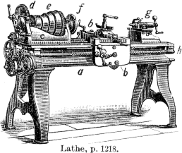
A lathe is a machine tool that rotates a workpiece about an axis of rotation to perform various operations such as cutting, sanding, knurling, drilling, deformation, facing, and turning, with tools that are applied to the workpiece to create an object with symmetry about that axis.

<span class="mw-page-title-main">Shaper</span> Machine tool which linearly cuts or grinds the workpiece

In machining, a shaper is a type of machine tool that uses linear relative motion between the workpiece and a single-point cutting tool to machine a linear toolpath. Its cut is analogous to that of a lathe, except that it is (archetypally) linear instead of helical.

<span class="mw-page-title-main">Metalworking</span> Process of making items from metal

Metalworking is the process of shaping and reshaping metals to create useful objects, parts, assemblies, and large scale structures. As a term it covers a wide and diverse range of processes, skills, and tools for producing objects on every scale: from huge ships, buildings, and bridges down to precise engine parts and delicate jewelry.

<span class="mw-page-title-main">Numerical control</span> Computer control of machine tools, lathes and milling machines, also used on 3D printers

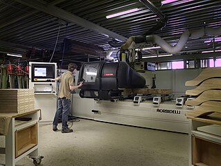
Numerical control is the automated control of machining tools by means of a computer. A CNC machine processes a piece of material to meet specifications by following coded programmed instructions and without a manual operator directly controlling the machining operation.

<span class="mw-page-title-main">Grinding machine</span> Machine tool used for grinding

A grinding machine, often shortened to grinder, is a power tool used for grinding. It is a type of machining using an abrasive wheel as the cutting tool. Each grain of abrasive on the wheel's surface cuts a small chip from the workpiece via shear deformation.

<span class="mw-page-title-main">Tool and cutter grinder</span>

A Tool and Cutter Grinder is used to sharpen milling cutters and tool bits along with a host of other cutting tools.

<span class="mw-page-title-main">Turning</span> Machining process

Turning is a machining process in which a cutting tool, typically a non-rotary tool bit, describes a helix toolpath by moving more or less linearly while the workpiece rotates.

<span class="mw-page-title-main">Engineer's spirit level</span>

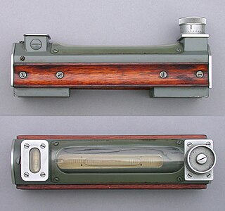
An engineer's spirit level is generally used to level machines, although they may also be used to level large workpieces on machines such as planers. Using gravity as a reference and checking a machine's axis of travel at several points, the level is used to ensure the machine's axis is straight. A perfectly level machine does not actually need to be achieved, unless the particular manufacturing process requires it. Spirit levels are also used in building construction by carpenters and masons.

<span class="mw-page-title-main">Lathe center</span>

A lathe center, often shortened to center, is a tool that has been ground to a point to accurately position a workpiece on an axis. They usually have an included angle of 60°, but in heavy machining situations an angle of 75° is used.

<span class="mw-page-title-main">Metal lathe</span> Machine tool used to remove material from a rotating workpiece

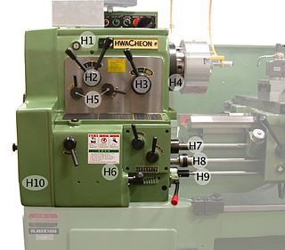
In machining, a metal lathe or metalworking lathe is a large class of lathes designed for precisely machining relatively hard materials. They were originally designed to machine metals; however, with the advent of plastics and other materials, and with their inherent versatility, they are used in a wide range of applications, and a broad range of materials. In machining jargon, where the larger context is already understood, they are usually simply called lathes, or else referred to by more-specific subtype names. These rigid machine tools remove material from a rotating workpiece via the movements of various cutting tools, such as tool bits and drill bits.

<span class="mw-page-title-main">Rotary table</span>

A rotary table is a precision work positioning device used in metalworking. It enables the operator to drill or cut work at exact intervals around a fixed axis. Some rotary tables allow the use of index plates for indexing operations, and some can also be fitted with dividing plates that enable regular work positioning at divisions for which indexing plates are not available. A rotary fixture used in this fashion is more appropriately called a dividing head.

<span class="mw-page-title-main">Coordinate-measuring machine</span> Device for measuring the geometry of objects

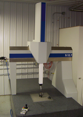
A coordinate measuring machine (CMM) is a device that measures the geometry of physical objects by sensing discrete points on the surface of the object with a probe. Various types of probes are used in CMMs, the most common being mechanical and laser sensors, though optical and white light sensor do exist. Depending on the machine, the probe position may be manually controlled by an operator or it may be computer controlled. CMMs typically specify a probe's position in terms of its displacement from a reference position in a three-dimensional Cartesian coordinate system. In addition to moving the probe along the X, Y, and Z axes, many machines also allow the probe angle to be controlled to allow measurement of surfaces that would otherwise be unreachable.

<span class="mw-page-title-main">Linear encoder</span>

A linear encoder is a sensor, transducer or readhead paired with a scale that encodes position. The sensor reads the scale in order to convert the encoded position into an analog or digital signal, which can then be decoded into position by a digital readout (DRO) or motion controller.

<span class="mw-page-title-main">Boring (manufacturing)</span> Process of enlarging an already-drilled hole with a single-point cutting tool

In machining, boring is the process of enlarging a hole that has already been drilled by means of a single-point cutting tool, such as in boring a gun barrel or an engine cylinder. Boring is used to achieve greater accuracy of the diameter of a hole, and can be used to cut a tapered hole. Boring can be viewed as the internal-diameter counterpart to turning, which cuts external diameters.

<span class="mw-page-title-main">Turret lathe</span> Metalworking lathe

The turret lathe is a form of metalworking lathe that is used for repetitive production of duplicate parts, which by the nature of their cutting process are usually interchangeable. It evolved from earlier lathes with the addition of the turret, which is an indexable toolholder that allows multiple cutting operations to be performed, each with a different cutting tool, in easy, rapid succession, with no need for the operator to perform set-up tasks in between or to control the toolpath. The latter is due to the toolpath's being controlled by the machine, either in jig-like fashion, via the mechanical limits placed on it by the turret's slide and stops, or via digitally-directed servomechanisms for computer numerical control lathes.

<span class="mw-page-title-main">Jig grinder</span>

A jig grinder is a machine tool used for grinding complex shapes and holes where the highest degrees of accuracy and finish are required.

<span class="mw-page-title-main">Tailstock</span>

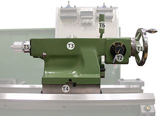
A tailstock, also known as a foot stock, is a device often used as part of an engineering lathe, wood-turning lathe, or used in conjunction with a rotary table on a milling machine.

<span class="mw-page-title-main">Grinding (abrasive cutting)</span> Machining process using a grinding wheel

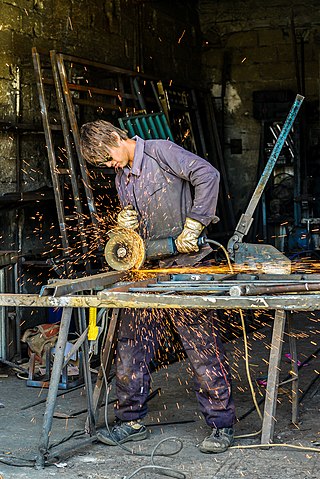
Grinding is a type of abrasive machining process which uses a grinding wheel as cutting tool.

<span class="mw-page-title-main">Spindle (tool)</span> Rotary unit of a machine tool


In machine tools, a spindle is a rotating axis of the machine, which often has a shaft at its heart. The shaft itself is called a spindle, but also, in shop-floor practice, the word often is used metonymically to refer to the entire rotary unit, including not only the shaft itself, but its bearings and anything attached to it.

<span class="mw-page-title-main">Milling (machining)</span> Removal of material from a workpiece using rotating tools

Milling is the process of machining using rotary cutters to remove material by advancing a cutter into a workpiece. This may be done by varying direction on one or several axes, cutter head speed, and pressure. Milling covers a wide variety of different operations and machines, on scales from small individual parts to large, heavy-duty gang milling operations. It is one of the most commonly used processes for machining custom parts to precise tolerances.

References

  1. OBERG et al., The Machinery's Hand Book. 26th edition, Industrial Press, New York, 2000. p. 630.