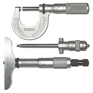
A micrometer, sometimes known as a micrometer screw gauge, is a device incorporating a calibrated screw widely used for accurate measurement of components in mechanical engineering and machining as well as most mechanical trades, along with other metrological instruments such as dial, vernier, and digital calipers. Micrometers are usually, but not always, in the form of calipers. The spindle is a very accurately machined screw and the object to be measured is placed between the spindle and the anvil. The spindle is moved by turning the ratchet knob or thimble until the object to be measured is lightly touched by both the spindle and the anvil.

A vernier scalever-NEE-er), named after Pierre Vernier, is a visual aid to take an accurate measurement reading between two graduation markings on a linear scale by using mechanical interpolation, thereby increasing resolution and reducing measurement uncertainty by using vernier acuity to reduce human estimation error. It may be found on many types of instrument measuring linear or angular quantities, but in particular on a vernier caliper, which measures lengths.

A lathe is a machine tool that rotates a workpiece about an axis of rotation to perform various operations such as cutting, sanding, knurling, drilling, deformation, facing, threading and turning, with tools that are applied to the workpiece to create an object with symmetry about that axis.

Henry Maudslay was an English machine tool innovator, tool and die maker, and inventor. He is considered a founding father of machine tool technology. His inventions were an important foundation for the Industrial Revolution.

A machine tool is a machine for handling or machining metal or other rigid materials, usually by cutting, boring, grinding, shearing, or other forms of deformations. Machine tools employ some sort of tool that does the cutting or shaping. All machine tools have some means of constraining the workpiece and provide a guided movement of the parts of the machine. Thus, the relative movement between the workpiece and the cutting tool is controlled or constrained by the machine to at least some extent, rather than being entirely "offhand" or "freehand". It is a power-driven metal cutting machine which assists in managing the needed relative motion between cutting tool and the job that changes the size and shape of the job material.

A theodolite is a precision optical instrument for measuring angles between designated visible points in the horizontal and vertical planes. The traditional use has been for land surveying, but it is also used extensively for building and infrastructure construction, and some specialized applications such as meteorology and rocket launching.
Henry Hindley (1701–1771) was an 18th-century clockmaker, watchmaker and maker of scientific instruments. He invented a screw-cutting lathe, a fusee-cutting engine and an improved wheel-cutting engine and made one of the first dividing engines, for the construction of accurately-graduated arcs on scientific instruments. He is thought to have made the world's first equatorially-mounted telescope, which can now be seen in Burton Constable Hall in East Yorkshire.

A clockmaker is an artisan who makes and/or repairs clocks. Since almost all clocks are now factory-made, most modern clockmakers only repair clocks. Modern clockmakers may be employed by jewellers, antique shops, and places devoted strictly to repairing clocks and watches. Clockmakers must be able to read blueprints and instructions for numerous types of clocks and time pieces that vary from antique clocks to modern time pieces in order to fix and make clocks or watches. The trade requires fine motor coordination as clockmakers must frequently work on devices with small gears and fine machinery.

Jesse Ramsden FRS FRSE was a British mathematician, astronomical and scientific instrument maker. His reputation was built on the engraving and design of dividing engines which allowed high accuracy measurements of angles and lengths in instruments. He produced instruments for astronomy that were especially well known for maritime use where they were needed for the measurement of latitudes and for his surveying instruments which were widely used for cartography and land survey both across the British Empire and outside. An achromatic eyepiece that he invented for telescopes and microscopes continues to be known as the Ramsden eyepiece.
Joseph Clement was a British engineer and industrialist, chiefly remembered as the maker of Charles Babbage's first difference engine, between 1824 and 1833.
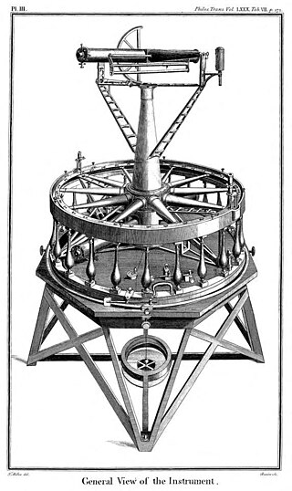
The Ramsden surveying instruments are those constructed by Jesse Ramsden and used in high precision geodetic surveys carried out in the period 1784 to 1853. This includes the five great theodolites—great in name, great in size and great in accuracy—used in surveys of Britain and other parts of the world. Ramsden also provided the equipment used in the measurement of the many base lines of these surveys and also the zenith telescope used in latitude determinations.
In machining, a metal lathe or metalworking lathe is a large class of lathes designed for precisely machining relatively hard materials. They were originally designed to machine metals; however, with the advent of plastics and other materials, and with their inherent versatility, they are used in a wide range of applications, and a broad range of materials. In machining jargon, where the larger context is already understood, they are usually simply called lathes, or else referred to by more-specific subtype names. These rigid machine tools remove material from a rotating workpiece via the movements of various cutting tools, such as tool bits and drill bits.

The octant, also called a reflecting quadrant, is a reflecting instrument used in navigation.

A rotary table is a precision work positioning device used in metalworking. It enables the operator to drill or cut work at exact intervals around a fixed axis. Some rotary tables allow the use of index plates for indexing operations, and some can also be fitted with dividing plates that enable regular work positioning at divisions for which indexing plates are not available. A rotary fixture used in this fashion is more appropriately called a dividing head.
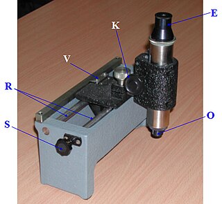
A travelling microscope is an instrument for measuring length with a resolution typically in the order of 0.01mm. The precision is such that better-quality instruments have measuring scales made from Invar to avoid misreadings due to thermal effects. The instrument comprises a microscope mounted on two rails fixed to, or part of a very rigid bed. The position of the microscope can be varied coarsely by sliding along the rails, or finely by turning a screw. The eyepiece is fitted with fine cross-hairs to fix a precise position, which is then read off the vernier scale. Some instruments, such as that produced in the 1960s by the Precision Tool and Instrument Company of Thornton Heath, Surrey, England, also measure vertically. The purpose of the microscope is to aim at reference marks with much higher accuracy than is possible using the naked eye. It is used in laboratories to measure the refractive index of flat specimens using the geometrical concepts of ray optics. It is also used to measure very short distances precisely, for example the diameter of a capillary tube. This mechanical instrument has now largely been superseded by electronic- and optically based measuring devices that are both very much more accurate and considerably cheaper to produce.
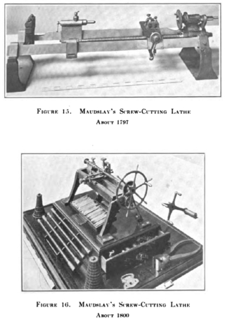
A screw-cutting lathe is a machine capable of cutting very accurate screw threads via single-point screw-cutting, which is the process of guiding the linear motion of the tool bit in a precisely known ratio to the rotating motion of the workpiece. This is accomplished by gearing the leadscrew to the spindle with a certain gear ratio for each thread pitch. Every degree of spindle rotation is matched by a certain distance of linear tool travel, depending on the desired thread pitch.

Transversals are a geometric construction on a scientific instrument to allow a graduation to be read to a finer degree of accuracy. Their use creates what is sometimes called a diagonal scale, an engineering measuring instrument which is composed of a set of parallel straight lines which are obliquely crossed by another set of straight lines. Diagonal scales are used to measure small fractions of the unit of measurement.
A graduation is a marking used to indicate points on a visual scale, which can be present on a container, a measuring device, or the axes of a line plot, usually one of many along a line or curve, each in the form of short line segments perpendicular to the line or curve. Often, some of these line segments are longer and marked with a numeral, such as every fifth or tenth graduation. The scale itself can be linear or nonlinear.
Reflecting instruments are those that use mirrors to enhance their ability to make measurements. In particular, the use of mirrors permits one to observe two objects simultaneously while measuring the angular distance between the objects. While reflecting instruments are used in many professions, they are primarily associated with celestial navigation as the need to solve navigation problems, in particular the problem of the longitude, was the primary motivation in their development.
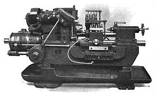
In metalworking and woodworking, an automatic lathe is a lathe with an automatically controlled cutting process. Automatic lathes were first developed in the 1870s and were mechanically controlled. From the advent of NC and CNC in the 1950s, the term automatic lathe has generally been used for only mechanically controlled lathes, although some manufacturers market Swiss-type CNC lathes as 'automatic'.


