Related Research Articles
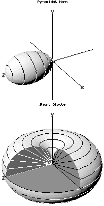
In the field of antenna design the term radiation pattern refers to the directional (angular) dependence of the strength of the radio waves from the antenna or other source.

In radio engineering, an antenna or aerial is an electronic device that converts an alternating electric current into radio waves, or radio waves into an electric current. It is the interface between radio waves propagating through space and electric currents moving in metal conductors, used with a transmitter or receiver. In transmission, a radio transmitter supplies an electric current to the antenna's terminals, and the antenna radiates the energy from the current as electromagnetic waves. In reception, an antenna intercepts some of the power of a radio wave in order to produce an electric current at its terminals, that is applied to a receiver to be amplified. Antennas are essential components of all radio equipment.

A parabolic antenna is an antenna that uses a parabolic reflector, a curved surface with the cross-sectional shape of a parabola, to direct the radio waves. The most common form is shaped like a dish and is popularly called a dish antenna or parabolic dish. The main advantage of a parabolic antenna is that it has high directivity. It functions similarly to a searchlight or flashlight reflector to direct radio waves in a narrow beam, or receive radio waves from one particular direction only. Parabolic antennas have some of the highest gains, meaning that they can produce the narrowest beamwidths, of any antenna type. In order to achieve narrow beamwidths, the parabolic reflector must be much larger than the wavelength of the radio waves used, so parabolic antennas are used in the high frequency part of the radio spectrum, at UHF and microwave (SHF) frequencies, at which the wavelengths are small enough that conveniently sized reflectors can be used.
Radio propagation is the behavior of radio waves as they travel, or are propagated, from one point to another in vacuum, or into various parts of the atmosphere. As a form of electromagnetic radiation, like light waves, radio waves are affected by the phenomena of reflection, refraction, diffraction, absorption, polarization, and scattering. Understanding the effects of varying conditions on radio propagation has many practical applications, from choosing frequencies for amateur radio communications, international shortwave broadcasters, to designing reliable mobile telephone systems, to radio navigation, to operation of radar systems.

Effective radiated power (ERP), synonymous with equivalent radiated power, is an IEEE standardized definition of directional radio frequency (RF) power, such as that emitted by a radio transmitter. It is the total power in watts that would have to be radiated by a half-wave dipole antenna to give the same radiation intensity as the actual source antenna at a distant receiver located in the direction of the antenna's strongest beam. ERP measures the combination of the power emitted by the transmitter and the ability of the antenna to direct that power in a given direction. It is equal to the input power to the antenna multiplied by the gain of the antenna. It is used in electronics and telecommunications, particularly in broadcasting to quantify the apparent power of a broadcasting station experienced by listeners in its reception area.
Radiation resistance is that part of an antenna's feedpoint electrical resistance caused by the emission of radio waves from the antenna. A radio transmitter applies a radio frequency alternating current to an antenna, which radiates the energy of the current as radio waves. Because the antenna is absorbing the energy it is radiating from the transmitter, the antenna's input terminals present a resistance to the current from the transmitter.

In radio and telecommunications a dipole antenna or doublet is one of the two simplest and most widely-used types of antenna; the other is the monopole. The dipole is any one of a class of antennas producing a radiation pattern approximating that of an elementary electric dipole with a radiating structure supporting a line current so energized that the current has only one node at each far end. A dipole antenna commonly consists of two identical conductive elements such as metal wires or rods. The driving current from the transmitter is applied, or for receiving antennas the output signal to the receiver is taken, between the two halves of the antenna. Each side of the feedline to the transmitter or receiver is connected to one of the conductors. This contrasts with a monopole antenna, which consists of a single rod or conductor with one side of the feedline connected to it, and the other side connected to some type of ground. A common example of a dipole is the "rabbit ears" television antenna found on broadcast television sets. All dipoles are electrically equivalent to two monopoles mounted end-to-end and fed with opposite phases, with the ground plane between them made "virtual" by the opposing monopole.

A whip antenna is an antenna consisting of a straight flexible wire or rod. The bottom end of the whip is connected to the radio receiver or transmitter. A whip antenna is a form of monopole antenna. The antenna is designed to be flexible so that it does not break easily, and the name is derived from the whip-like motion that it exhibits when disturbed. Whip antennas for portable radios are often made of a series of interlocking telescoping metal tubes, so they can be retracted when not in use. Longer whips, made for mounting on vehicles and structures, are made of a flexible fiberglass rod around a wire core and can be up to 11 m long.

Radio masts and towers are typically tall structures designed to support antennas for telecommunications and broadcasting, including television. There are two main types: guyed and self-supporting structures. They are among the tallest human-made structures. Masts are often named after the broadcasting organizations that originally built them or currently use them.

A mast radiator is a radio mast or tower in which the metal structure itself is energized and functions as an antenna. This design, first used widely in the 1930s, is commonly used for transmitting antennas operating at low frequencies, in the LF and MF bands, in particular those used for AM radio broadcasting stations. The conductive steel mast is electrically connected to the transmitter. Its base is usually mounted on a nonconductive support to insulate it from the ground. A mast radiator is a form of monopole antenna.

A ‘T’-antenna, ‘T’-aerial, or flat-top antenna is a monopole radio antenna consisting of one or more horizontal wires suspended between two supporting radio masts or buildings and insulated from them at the ends. A vertical wire is connected to the center of the horizontal wires and hangs down close to the ground, connected to the transmitter or receiver. The shape of the antenna resembles the letter "T", hence the name. The transmitter power is applied, or the receiver is connected, between the bottom of the vertical wire and a ground connection.

A loop antenna is a radio antenna consisting of a loop or coil of wire, tubing, or other electrical conductor, that for transmitting is usually fed by a balanced power source or for receiving feeds a balanced load. Within this physical description there are two distinct types:
Near vertical incidence skywave, or NVIS, is a skywave radio-wave propagation path that provides usable signals in the medium distances range — usually 0–650 km. It is used for military and paramilitary communications, broadcasting, especially in the tropics, and by radio amateurs for nearby contacts circumventing line-of-sight barriers. The radio waves travel near-vertically upwards into the ionosphere, where they are refracted back down and can be received within a circular region up to 650 km from the transmitter. If the frequency is too high, refraction is insufficient to return the signal to earth and if it is too low, absorption in the ionospheric D layer may reduce the signal strength.
A monopole antenna is a class of radio antenna consisting of a straight rod-shaped conductor, often mounted perpendicularly over some type of conductive surface, called a ground plane. The driving signal from the transmitter is applied, or for receiving antennas the output signal to the receiver is taken, between the lower end of the monopole and the ground plane. One side of the antenna feedline is attached to the lower end of the monopole, and the other side is attached to the ground plane, which is often the Earth. This contrasts with a dipole antenna which consists of two identical rod conductors, with the signal from the transmitter applied between the two halves of the antenna.
In RF engineering, radial has three distinct meanings, both referring to lines which radiate from a radio antenna, but neither meaning is related to the other.

The folded unipole antenna is a type of monopole mast radiator antenna used as a transmitting antenna mainly in the medium wave band for AM radio broadcasting stations. It consists of a vertical metal rod or mast mounted over and connected at its base to a grounding system consisting of buried wires. The mast is surrounded by a "skirt" of vertical wires electrically attached at or near the top of the mast. The skirt wires are connected by a metal ring near the mast base, and the feedline feeding power from the transmitter is connected between the ring and the ground.

An umbrella antenna is a capacitively top-loaded wire monopole antenna, consisting in most cases of a mast fed at the ground end, to which a number of radial wires are connected at the top, sloping downwards. One side of the feedline supplying power from the transmitter is connected to the mast, and the other side to a ground (Earthing) system of radial wires buried in the earth under the antenna. They are used as transmitting antennas below 1 MHz, in the MF, LF and particularly the VLF bands, at frequencies sufficiently low that it is impractical or infeasible to build a full size quarter-wave monopole antenna. The outer end of each radial wire, sloping down from the top of the antenna, is connected by an insulator to a supporting rope or cable anchored to the ground; the radial wires can also support the mast as guy wires. The radial wires make the antenna look like the wire frame of a giant umbrella hence the name.

In radio communication, a ground dipole, also referred to as an earth dipole antenna, transmission line antenna, and in technical literature as a horizontal electric dipole (HED), is a huge, specialized type of radio antenna that radiates extremely low frequency (ELF) electromagnetic waves. It is the only type of transmitting antenna that can radiate practical amounts of power in the frequency range of 3 Hz to 3 kHz, commonly called ELF waves. A ground dipole consists of two ground electrodes buried in the earth, separated by tens to hundreds of kilometers, linked by overhead transmission lines to a power plant transmitter located between them. Alternating current electricity flows in a giant loop between the electrodes through the ground, radiating ELF waves, so the ground is part of the antenna. To be most effective, ground dipoles must be located over certain types of underground rock formations. The idea was proposed by U.S. Dept. of Defense physicist Nicholas Christofilos in 1959.

A halo antenna, or halo, is a center-fed 1 /2 wavelength dipole antenna, which has been bent into a circle, with a break directly opposite the feed point. The dipole's ends are close, but do not touch, and their crossections may be broadened to form an air capacitor, whose spacing is used to adjust the antenna's resonant frequency. Most often mounted horizontally, this antenna's radiation is then approximately omnidirectional and horizontally polarized.
In radio systems, many different antenna types are used whose properties are especially crafted for particular applications.
References
![]() This article incorporates public domain material from Federal Standard 1037C. General Services Administration. Archived from the original on 2022-01-22. (in support of MIL-STD-188).
This article incorporates public domain material from Federal Standard 1037C. General Services Administration. Archived from the original on 2022-01-22. (in support of MIL-STD-188).
| | This article related to telecommunications is a stub. You can help Wikipedia by expanding it. |