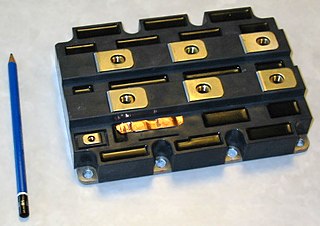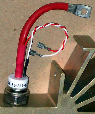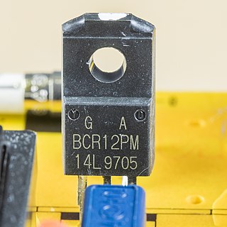
A transistor is a semiconductor device used to amplify or switch electrical signals and power. It is one of the basic building blocks of modern electronics. It is composed of semiconductor material, usually with at least three terminals for connection to an electronic circuit. A voltage or current applied to one pair of the transistor's terminals controls the current through another pair of terminals. Because the controlled (output) power can be higher than the controlling (input) power, a transistor can amplify a signal. Some transistors are packaged individually, but many more in miniature form are found embedded in integrated circuits. Because transistors are the key active components in practically all modern electronics, many people consider them one of the 20th century's greatest inventions.

The metal–oxide–semiconductor field-effect transistor is a type of field-effect transistor (FET), most commonly fabricated by the controlled oxidation of silicon. It has an insulated gate, the voltage of which determines the conductivity of the device. This ability to change conductivity with the amount of applied voltage can be used for amplifying or switching electronic signals. The term metal–insulator–semiconductor field-effect transistor (MISFET) is almost synonymous with MOSFET. Another near-synonym is insulated-gate field-effect transistor (IGFET).
A unijunction transistor (UJT) is a three-lead electronic semiconductor device with only one junction. It acts exclusively as an electrically controlled switch.

An insulated-gate bipolar transistor (IGBT) is a three-terminal power semiconductor device primarily forming an electronic switch. It was developed to combine high efficiency with fast switching. It consists of four alternating layers (P–N–P–N) that are controlled by a metal–oxide–semiconductor (MOS) gate structure.

A thyristor is a solid-state semiconductor device with four layers of alternating P- and N-type materials used for high-power applications. It acts as a bistable switch. There are two designs, differing in what triggers the conducting state. In a three-lead thyristor, a small current on its gate lead controls the larger current of the anode-to-cathode path. In a two-lead thyristor, conduction begins when the potential difference between the anode and cathode themselves is sufficiently large. The thyristor continues conducting until the voltage across the device is reverse-biased or the voltage is removed, or through the control gate signal on newer types.

A silicon controlled rectifier or semiconductor controlled rectifier is a four-layer solid-state current-controlling device. The name "silicon controlled rectifier" is General Electric's trade name for a type of thyristor. The principle of four-layer p–n–p–n switching was developed by Moll, Tanenbaum, Goldey, and Holonyak of Bell Laboratories in 1956. The practical demonstration of silicon controlled switching and detailed theoretical behavior of a device in agreement with the experimental results was presented by Dr Ian M. Mackintosh of Bell Laboratories in January 1958. The SCR was developed by a team of power engineers led by Gordon Hall and commercialized by Frank W. "Bill" Gutzwiller in 1957.

A TRIAC is a three-terminal electronic component that conducts current in either direction when triggered. The term TRIAC is a genericised trademark.

The DIAC is a diode that conducts electrical current only after its breakover voltage, VBO, has been reached momentarily. Three, four, and five layer structures may be used. Behavior is similar to the voltage breakdown of a triac without a gate terminal.

The integrated gate-commutated thyristor (IGCT) is a power semiconductor electronic device, used for switching electric current in industrial equipment. It is related to the gate turn-off (GTO) thyristor.
A power semiconductor device is a semiconductor device used as a switch or rectifier in power electronics. Such a device is also called a power device or, when used in an integrated circuit, a power IC.

IC power-supply pins denote a voltage and current supply terminals in electric, electronics engineering, and in Integrated circuit design. Integrated circuits (ICs) have at least two pins that connect to the power rails of the circuit in which they are installed. These are known as the power-supply pins. However, the labeling of the pins varies by IC family and manufacturer. The double subscript notation usually corresponds to a first letter in a given IC family (transistors) notation of the terminals.

A crowbar circuit is an electrical circuit used for preventing an overvoltage or surge condition of a power supply unit from damaging the circuits attached to the power supply. It operates by putting a short circuit or low resistance path across the voltage output (Vo), like dropping a crowbar across the output terminals of the power supply. Crowbar circuits are frequently implemented using a thyristor, TRIAC, trisil or thyratron as the shorting device. Once triggered, they depend on the current-limiting circuitry of the power supply or, if that fails, the blowing of the line fuse or tripping the circuit breaker.
MOS composite static induction thyristor is a combination of a MOS transistor connected in cascode relation to the SI-thyristor.

A power MOSFET is a specific type of metal–oxide–semiconductor field-effect transistor (MOSFET) designed to handle significant power levels. Compared to the other power semiconductor devices, such as an insulated-gate bipolar transistor (IGBT) or a thyristor, its main advantages are high switching speed and good efficiency at low voltages. It shares with the IGBT an isolated gate that makes it easy to drive. They can be subject to low gain, sometimes to a degree that the gate voltage needs to be higher than the voltage under control.
Open collector, open drain, open emitter, and open source refer to integrated circuit (IC) output pin configurations that process the IC's internal function though a transistor with an exposed terminal that is internally unconnected. One of the IC's internal high or low voltage rails typically connects to another terminal of that transistor. When the transistor is off, the output is internally disconnected from any internal power rail, a state called "high-impedance" (Hi-Z). Open outputs configurations thus differ from push–pull outputs, which use a pair of transistors to output a specific voltage or current.
In the field of electronics, a technique where part of the output of a system is used at startup can be described as bootstrapping.

A gate turn-off thyristor (GTO) is a special type of thyristor, which is a high-power semiconductor device. It was invented by General Electric. GTOs, as opposed to normal thyristors, are fully controllable switches which can be turned on and off by their gate lead.

An MOS-controlled thyristor (MCT) is a voltage-controlled fully controllable thyristor, controlled by MOSFETs. It was invented by V.A.K. Temple in 1984, and was principally similar to the earlier insulated-gate bipolar transistor (IGBT). MCTs are similar in operation to GTO thyristors, but have voltage controlled insulated gates. They have two MOSFETs of opposite conductivity types in their equivalent circuits. One is responsible for turn-on and the other for turn-off. A thyristor with only one MOSFET in its equivalent circuit, which can only be turned on, is called an MOS-gated thyristor.
An HVDC converter converts electric power from high voltage alternating current (AC) to high-voltage direct current (HVDC), or vice versa. HVDC is used as an alternative to AC for transmitting electrical energy over long distances or between AC power systems of different frequencies. HVDC converters capable of converting up to two gigawatts (GW) and with voltage ratings of up to 900 kilovolts (kV) have been built, and even higher ratings are technically feasible. A complete converter station may contain several such converters in series and/or parallel to achieve total system DC voltage ratings of up to 1,100 kV.

The field-effect transistor (FET) is a type of transistor that uses an electric field to control the flow of current in a semiconductor. It comes in two types: junction FET (JFET) and metal-oxide-semiconductor FET (MOSFET). FETs have three terminals: source, gate, and drain. FETs control the flow of current by the application of a voltage to the gate, which in turn alters the conductivity between the drain and source.


