
The Rockwell scale is a hardness scale based on indentation hardness of a material. The Rockwell test measures the depth of penetration of an indenter under a large load compared to the penetration made by a preload. There are different scales, denoted by a single letter, that use different loads or indenters. The result is a dimensionless number noted as HRA, HRB, HRC, etc., where the last letter is the respective Rockwell scale. Larger numbers correspond to harder materials.

Infrared thermography (IRT), thermal video and/or thermal imaging, is a process where a thermal camera captures and creates an image of an object by using infrared radiation emitted from the object in a process, which are examples of infrared imaging science. Thermographic cameras usually detect radiation in the long-infrared range of the electromagnetic spectrum and produce images of that radiation, called thermograms. Since infrared radiation is emitted by all objects with a temperature above absolute zero according to the black body radiation law, thermography makes it possible to see one's environment with or without visible illumination. The amount of radiation emitted by an object increases with temperature; therefore, thermography allows one to see variations in temperature. When viewed through a thermal imaging camera, warm objects stand out well against cooler backgrounds; humans and other warm-blooded animals become easily visible against the environment, day or night. As a result, thermography is particularly useful to the military and other users of surveillance cameras.

In mechanics, compressive strength is the capacity of a material or structure to withstand loads tending to reduce size. In other words, compressive strength resists compression, whereas tensile strength resists tension. In the study of strength of materials, tensile strength, compressive strength, and shear strength can be analyzed independently.

A strain gauge is a device used to measure strain on an object. Invented by Edward E. Simmons and Arthur C. Ruge in 1938, the most common type of strain gauge consists of an insulating flexible backing which supports a metallic foil pattern. The gauge is attached to the object by a suitable adhesive, such as cyanoacrylate. As the object is deformed, the foil is deformed, causing its electrical resistance to change. This resistance change, usually measured using a Wheatstone bridge, is related to the strain by the quantity known as the gauge factor.
Resistance thermometers, also called resistance temperature detectors (RTDs), are sensors used to measure temperature. Many RTD elements consist of a length of fine wire wrapped around a heat-resistant ceramic or glass core but other constructions are also used. The RTD wire is a pure material, typically platinum (Pt), nickel (Ni), or copper (Cu). The material has an accurate resistance/temperature relationship which is used to provide an indication of temperature. As RTD elements are fragile, they are often housed in protective probes.
The Vickers hardness test was developed in 1921 by Robert L. Smith and George E. Sandland at Vickers Ltd as an alternative to the Brinell method to measure the hardness of materials. The Vickers test is often easier to use than other hardness tests since the required calculations are independent of the size of the indenter, and the indenter can be used for all materials irrespective of hardness. The basic principle, as with all common measures of hardness, is to observe a material's ability to resist plastic deformation from a standard source. The Vickers test can be used for all metals and has one of the widest scales among hardness tests. The unit of hardness given by the test is known as the Vickers Pyramid Number (HV) or Diamond Pyramid Hardness (DPH). The hardness number can be converted into units of pascals, but should not be confused with pressure, which uses the same units. The hardness number is determined by the load over the surface area of the indentation and not the area normal to the force, and is therefore not pressure.

In materials science and solid mechanics, residual stresses are stresses that remain in a solid material after the original cause of the stresses has been removed. Residual stress may be desirable or undesirable. For example, laser peening imparts deep beneficial compressive residual stresses into metal components such as turbine engine fan blades, and it is used in toughened glass to allow for large, thin, crack- and scratch-resistant glass displays on smartphones. However, unintended residual stress in a designed structure may cause it to fail prematurely.
A load cell converts a force such as tension, compression, pressure, or torque into a signal that can be measured and standardized. It is a force transducer. As the force applied to the load cell increases, the signal changes proportionally. The most common types of load cells are pneumatic, hydraulic, and strain gauge types for industrial applications. Typical non-electronic bathroom scales are a widespread example of a mechanical displacement indicator where the applied weight (force) is indicated by measuring the deflection of springs supporting the load platform, technically a "load cell".

An infrared thermometer is a thermometer which infers temperature from a portion of the thermal radiation sometimes called black-body radiation emitted by the object being measured. They are sometimes called laser thermometers as a laser is used to help aim the thermometer, or non-contact thermometers or temperature guns, to describe the device's ability to measure temperature from a distance. By knowing the amount of infrared energy emitted by the object and its emissivity, the object's temperature can often be determined within a certain range of its actual temperature. Infrared thermometers are a subset of devices known as "thermal radiation thermometers".

The three-point bending flexural test provides values for the modulus of elasticity in bending , flexural stress , flexural strain and the flexural stress–strain response of the material. This test is performed on a universal testing machine with a three-point or four-point bend fixture. The main advantage of a three-point flexural test is the ease of the specimen preparation and testing. However, this method has also some disadvantages: the results of the testing method are sensitive to specimen and loading geometry and strain rate.

A universal testing machine (UTM), also known as a universal tester, universal tensile machine, materials testing machine, materials test frame, is used to test the tensile strength (pulling) and compressive strength (pushing), flexural strength, bending, shear, hardness, and torsion testing, providing valuable data for designing and ensuring the quality of materials. An earlier name for a tensile testing machine is a tensometer. The "universal" part of the name reflects that it can perform many standard tests application on materials, components, and structures.
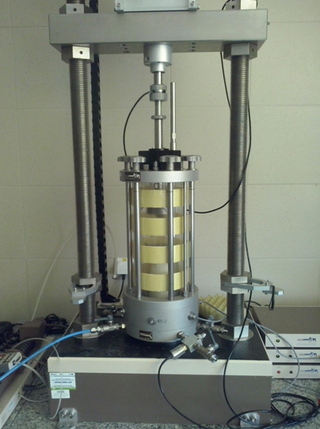
A triaxial shear test is a common method to measure the mechanical properties of many deformable solids, especially soil and rock, and other granular materials or powders. There are several variations on the test.

A dilatometer is a scientific instrument that measures volume changes caused by a physical or chemical process. A familiar application of a dilatometer is the mercury-in-glass thermometer, in which the change in volume of the liquid column is read from a graduated scale. Because mercury has a fairly constant rate of expansion over ambient temperature ranges, the volume changes are directly related to temperature.

The international roughness index (IRI) is the roughness index most commonly obtained from measured longitudinal road profiles. It is calculated using a quarter-car vehicle math model, whose response is accumulated to yield a roughness index with units of slope. Although a universal term, IRI is calculated per wheelpath, but can be expanded to a Mean Roughness Index (MRI) when both wheelpath profiles are collected. This performance measure has less stochasticity and subjectivity in comparison to other pavement performance indicators, such as PCI, but it is not completely devoid of randomness. The sources of variability in IRI data include the difference among the readings of different runs of the test vehicle and the difference between the readings of the right and left wheel paths. Despite these facts, since its introduction in 1986, the IRI has become the road roughness index most commonly used worldwide for evaluating and managing road systems.
Rising Step Load Testing is a testing system that can apply loads in tension or bending to evaluate hydrogen-induced cracking. It was specifically designed to conduct the accelerated ASTM F1624 step-modified, slow strain rate tests on a variety of test coupons or structural components. It can also function to conduct conventional ASTM E8 tensile tests; ASTM F519 200-hr Sustained Load Tests with subsequent programmable step loads to rupture for increased reliability; and ASTM G129 Slow Strain Rate Tensile tests.

Tensile testing, also known as tension testing, is a fundamental materials science and engineering test in which a sample is subjected to a controlled tension until failure. Properties that are directly measured via a tensile test are ultimate tensile strength, breaking strength, maximum elongation and reduction in area. From these measurements the following properties can also be determined: Young's modulus, Poisson's ratio, yield strength, and strain-hardening characteristics. Uniaxial tensile testing is the most commonly used for obtaining the mechanical characteristics of isotropic materials. Some materials use biaxial tensile testing. The main difference between these testing machines being how load is applied on the materials.

The hole drilling method is a method for measuring residual stresses, in a material. Residual stress occurs in a material in the absence of external loads. Residual stress interacts with the applied loading on the material to affect the overall strength, fatigue, and corrosion performance of the material. Residual stresses are measured through experiments. The hole drilling method is one of the most used methods for residual stress measurement.
Digital image correlation analyses have applications in material property characterization, displacement measurement, and strain mapping. As such, DIC is becoming an increasingly popular tool when evaluating the thermo-mechanical behavior of electronic components and systems.
Michael A. Sutton is an American Engineering professor. He is Carolina Distinguished Professor and Distinguished Professor Emeritus of Mechanical Engineering at the University of South Carolina-Columbia. He served as Chairperson of Mechanical Engineering and Chair of the University Tenure and Promotion Committee. In 1998, Dr. Sutton co-founded Correlated Solutions, Inc. in Columbia, SC, and he still serves as its CSO.
A compressometer is a device used to determine the strain or deformation of a specimen while measuring the compressive strength of concrete specimens, generally a cylinder. It can be used for rock, concrete, soils, and other materials. For concrete, the device usually comprises two steel rings for clamping to the specimen and two gauge length bars attached to the ring. When the compressive load is applied, the strain value is registered from the compressometer. Generally, a data logger is used to record the strain.


