
The Fairbairn-Beeley boiler was a design of fire-tube stationary boiler developed in the late 19th century. It takes its name from its two developers, Sir William Fairbairn and Thomas Beeley [2]
The Fairbairn-Beeley boiler was a design of fire-tube stationary boiler developed in the late 19th century. It takes its name from its two developers, Sir William Fairbairn and Thomas Beeley [2]
Sir William Fairbairn (1789–1874) was one of the most mathematically inclined of the Victorian mechanical engineers. Assisted by his mathematical analyst Eaton Hodgkinson, he conducted the first theoretical analysis of the stress in cylinders. Their first interest was in studying the design and failures of large-diameter Lancashire boilers. [3] Fairbairn realised that the hoop stress was twice the longitudinal stress, and that both were related to the diameter of pressure vessels.
Thomas Beeley (1833–1908) was the proprietor of the well-known Manchester boilermakers, Hyde Junction Iron Works, later known as Thomas Beeley and Son. [4] [lower-roman 1]
Fairbairn's work had shown the benefits of reducing the diameter of a boiler's external shell as a means of reducing the forces upon it. The overall vertical height of the boiler could not be reduced, as this represented the clear steam space above the water level which is important to avoid the risk of priming. Oval boilers had already been tried to achieve this vertical extension, but pressure within them tended to force them into a more cylindrical shape; repeated cycling like this led to increased corrosion along the riveted joints and fatigue failures.
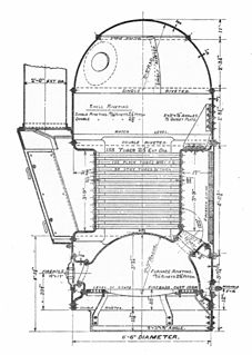
Fairbairn's innovation was to use three cylindrical shells of small diameter, stacked vertically. The central drum was a mixed steam and water space with the water level midway through it. A typical size would be 5 or 6 feet in diameter and 20 feet long. A smaller drum above this acted as a steam space, the narrow communicating pipes between them also helping to stop carryover with steam.
The lowest drum of the three provided the heating surface. This was almost entirely filled with a cylindrical corrugated furnace. A length, approximately one diameter, was filled with a number of, around 60, small diameter fire-tubes. Compared to previous large-flued stationary boilers, such as the Lancashire or Galloway boilers, this was a larger heating area in a very compact space. [lower-roman 2] The tubes were still short, compared to locomotive boilers, and offered good gasflow for the exhaust gases without needing additional exhaust draughting. The waterspace around the furnace was just thick enough to allow good circulation and leave space for mud to build up, but otherwise keeping the water volume to a minimum. This led to rapid heating of the water and so good thermosyphon circulation into the central drum above. This circulation was encouraged by the provision of a number of pipe connections between the drums. Each connection had an internal divider to give two separated pipes, the downcomer being just a short pipe from the lower part of the drum, but the outlet of the upwell pipe was raised above the water level and turned over in an outlet nozzle, promoting mixing of the hottest water and avoiding the formation of a stratified hot layer above cold. Examples showed a single large diameter fire-tube at the base of the tubeplate and a full-diameter section of furnace beyond the fire-tube nest, but the purpose of either of these features is unclear. Like the larger Lancashire boilers, exhaust gases were then led through brick flues around the outside of the boiler. [6]
An outwardly similar design had been used earlier, with the elephant boiler of the 1840s. [7] [8] This used three cylindrical shells, with two directly heated [lower-roman 3] cylinders below a single central steam drum. It pre-dated Fairbairn's theoretical work though and the multiple drums were to provide extra heating surface area, rather than for structural reasons. These boilers were more a development of the egg-ended boiler, as externally heated drums without fire-tubes.
Although never a widely used boiler, this type was adopted towards the end of the 19th century for dynamically changing loads, where a more responsive boiler than the Lancashire was needed. One field that adopted them was that of the city-scale hydraulic power networks. The London Hydraulic Power Company installed them at their City Road and Wapping Hydraulic Power Stations. [9] [10] They were also used to power early electricity generators for mills and factories, in the period between the Lancashire boiler and the first water-tube boilers.

A boiler is a closed vessel in which fluid is heated. The fluid does not necessarily boil. The heated or vaporized fluid exits the boiler for use in various processes or heating applications, including water heating, central heating, boiler-based power generation, cooking, and sanitation.

A fire-tube boiler is a type of boiler in which hot gases pass from a fire through one or more tubes running through a sealed container of water. The heat of the gases is transferred through the walls of the tubes by thermal conduction, heating the water and ultimately creating steam.

A thermal power station is a power station in which heat energy is converted to electricity. Typically, water is heated into steam, which is used to drive an electrical generator. After it passes through the turbine the steam is condensed in a steam condenser and recycled to where it was heated. This is known as a Rankine cycle. The greatest variation in the design of thermal power stations is due to the different heat sources: fossil fuel, nuclear energy, solar energy, biofuels, and waste incineration are all used. Certain thermal power stations are also designed to produce heat for industrial purposes, for district heating, or desalination of water, in addition to generating electrical power.

A boiler or steam generator is a device used to create steam by applying heat energy to water. Although the definitions are somewhat flexible, it can be said that older steam generators were commonly termed boilers and worked at low to medium pressure but, at pressures above this, it is more usual to speak of a steam generator.

A "Scotch" marine boiler is a design of steam boiler best known for its use on ships.

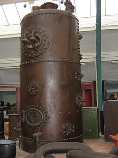
A shell or flued boiler is an early and relatively simple form of boiler used to make steam, usually for the purpose of driving a steam engine. The design marked a transitional stage in boiler development, between the early haystack boilers and the later multi-tube fire-tube boilers. A flued boiler is characterized by a large cylindrical boiler shell forming a tank of water, traversed by one or more large flues containing the furnace. These boilers appeared around the start of the 19th century and some forms remain in service today. Although mostly used for static steam plants, some were used in early steam vehicles, railway locomotives and ships.
A vertical boiler with horizontal fire-tubes is a type of small vertical boiler, used to generate steam for small machinery. It is characterised by having many narrow fire-tubes, running horizontally.

Yarrow boilers are an important class of high-pressure water-tube boilers. They were developed by Yarrow & Co. (London), Shipbuilders and Engineers and were widely used on ships, particularly warships.

The Stirling boiler is an early form of water-tube boiler, used to generate steam in large land-based stationary plants. Although widely used around 1900, it has now fallen from favour and is rarely seen.
Boilers for generating steam or hot water have been designed in countless shapes, sizes and configurations. An extensive terminology has evolved to describe their common features. This glossary provides definitions for these terms.
A Field-tube boiler is a form of water-tube boiler where the water tubes are single-ended. The tubes are closed at one end, and they contain a concentric inner tube. Flow is thus separated into the colder inner flow down the tube and the heated flow upwards through the outer sleeve. As Field tubes are thus dependent on thermo-syphon flow within the tube, they must thus always have some vertical height to encourage the flow. In most designs they are mounted near-vertically, to encourage this.
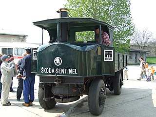
The Sentinel boiler was a design of vertical boiler, fitted to the numerous steam waggons built by the Sentinel Waggon Works.

Three-drum boilers are a class of water-tube boiler used to generate steam, typically to power ships. They are compact and of high evaporative power, factors that encourage this use. Other boiler designs may be more efficient, although bulkier, and so the three-drum pattern was rare as a land-based stationary boiler.

A transverse boiler is a boiler used to generate steam to power a vehicle. Unlike other boilers, its external drum is mounted transversely across the vehicle.
A cross-tube boiler was the most common form of small vertical boiler. They were widely used, in the age of steam, as a small donkey boiler, for the independent power of winches, steam cranes etc.

A launch-type, gunboat or horizontal multitubular boiler is a form of small steam boiler. It consists of a cylindrical horizontal shell with a cylindrical furnace and fire-tubes within this.

Spiral water-tube boilers are a family of vertical water-tube boilers. Their steam generating tubes are narrow spiral tubes, arranged in circular fashion around a central vertical water drum.

The Johnson boiler is a water-tube boiler used for ship propulsion.

A steam generator is a form of low water-content boiler, similar to a flash steam boiler. The usual construction is as a spiral coil of water-tube, arranged as a single, or monotube, coil. Circulation is once-through and pumped under pressure, as a forced-circulation boiler. The narrow-tube construction, without any large-diameter drums or tanks, means that they are safe from the effects of explosion, even if worked at high pressures. The pump flowrate is adjustable, according to the quantity of steam required at that time. The burner output is throttled to maintain a constant working temperature. The burner output required varies according to the quantity of water being evaporated: this can be either adjusted by open-loop control according to the pump throughput, or by a closed-loop control to maintain the measured temperature.

A thimble tube boiler is a form of steam boiler, usually provided as an auxiliary boiler or heat-recovery boiler. They are vertical in orientation and would be considered a form of water-tube boiler.