Related Research Articles

Ductility is a mechanical property commonly described as a material's amenability to drawing. In materials science, ductility is defined by the degree to which a material can sustain plastic deformation under tensile stress before failure. Ductility is an important consideration in engineering and manufacturing. It defines a material's suitability for certain manufacturing operations and its capacity to absorb mechanical overload. Some metals that are generally described as ductile include gold and copper, while platinum is the most ductile of all metals in pure form. However, not all metals experience ductile failure as some can be characterized with brittle failure like cast iron. Polymers generally can be viewed as ductile materials as they typically allow for plastic deformation.

Ultimate tensile strength is the maximum stress that a material can withstand while being stretched or pulled before breaking. In brittle materials the ultimate tensile strength is close to the yield point, whereas in ductile materials the ultimate tensile strength can be higher.
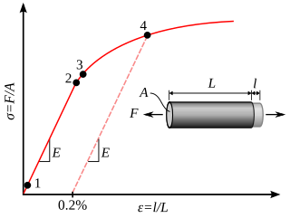
In engineering, deformation refers to the change in size or shape of an object. Displacements are the absolute change in position of a point on the object. Deflection is the relative change in external displacements on an object. Strain is the relative internal change in shape of an infinitesimally small cube of material and can be expressed as a non-dimensional change in length or angle of distortion of the cube. Strains are related to the forces acting on the cube, which are known as stress, by a stress-strain curve. The relationship between stress and strain is generally linear and reversible up until the yield point and the deformation is elastic. The linear relationship for a material is known as Young's modulus. Above the yield point, some degree of permanent distortion remains after unloading and is termed plastic deformation. The determination of the stress and strain throughout a solid object is given by the field of strength of materials and for a structure by structural analysis.
In physics and materials science, plasticity is the ability of a solid material to undergo permanent deformation, a non-reversible change of shape in response to applied forces. For example, a solid piece of metal being bent or pounded into a new shape displays plasticity as permanent changes occur within the material itself. In engineering, the transition from elastic behavior to plastic behavior is known as yielding.

In engineering and materials science, a stress–strain curve for a material gives the relationship between stress and strain. It is obtained by gradually applying load to a test coupon and measuring the deformation, from which the stress and strain can be determined. These curves reveal many of the properties of a material, such as the Young's modulus, the yield strength and the ultimate tensile strength.

Fracture is the appearance of a crack or complete separation of an object or material into two or more pieces under the action of stress. The fracture of a solid usually occurs due to the development of certain displacement discontinuity surfaces within the solid. If a displacement develops perpendicular to the surface, it is called a normal tensile crack or simply a crack; if a displacement develops tangentially, it is called a shear crack, slip band or dislocation.
In materials science, superplasticity is a state in which solid crystalline material is deformed well beyond its usual breaking point, usually over about 400% during tensile deformation. Such a state is usually achieved at high homologous temperature. Examples of superplastic materials are some fine-grained metals and ceramics. Other non-crystalline materials (amorphous) such as silica glass and polymers also deform similarly, but are not called superplastic, because they are not crystalline; rather, their deformation is often described as Newtonian fluid. Superplastically deformed material gets thinner in a very uniform manner, rather than forming a "neck" that leads to fracture. Also, the formation of microvoids, which is another cause of early fracture, is inhibited. Superplasticity must not be confused with superelasticity.
The field of strength of materials typically refers to various methods of calculating the stresses and strains in structural members, such as beams, columns, and shafts. The methods employed to predict the response of a structure under loading and its susceptibility to various failure modes takes into account the properties of the materials such as its yield strength, ultimate strength, Young's modulus, and Poisson's ratio. In addition, the mechanical element's macroscopic properties such as its length, width, thickness, boundary constraints and abrupt changes in geometry such as holes are considered.

In mechanics, compressive strength is the capacity of a material or structure to withstand loads tending to reduce size. In other words, compressive strength resists compression, whereas tensile strength resists tension. In the study of strength of materials, tensile strength, compressive strength, and shear strength can be analyzed independently.

In materials science, work hardening, also known as strain hardening, is the strengthening of a metal or polymer by plastic deformation. Work hardening may be desirable, undesirable, or inconsequential, depending on the context.
In engineering and materials science, necking is a mode of tensile deformation where relatively large amounts of strain localize disproportionately in a small region of the material. The resulting prominent decrease in local cross-sectional area provides the basis for the name "neck". Because the local strains in the neck are large, necking is often closely associated with yielding, a form of plastic deformation associated with ductile materials, often metals or polymers. Once necking has begun, the neck becomes the exclusive location of yielding in the material, as the reduced area gives the neck the largest local stress.
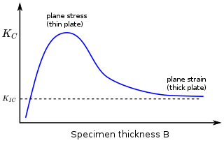
In materials science, fracture toughness is the critical stress intensity factor of a sharp crack where propagation of the crack suddenly becomes rapid and unlimited. A component's thickness affects the constraint conditions at the tip of a crack with thin components having plane stress conditions and thick components having plane strain conditions. Plane strain conditions give the lowest fracture toughness value which is a material property. The critical value of stress intensity factor in mode I loading measured under plane strain conditions is known as the plane strain fracture toughness, denoted . When a test fails to meet the thickness and other test requirements that are in place to ensure plane strain conditions, the fracture toughness value produced is given the designation . Fracture toughness is a quantitative way of expressing a material's resistance to crack propagation and standard values for a given material are generally available.
Methods have been devised to modify the yield strength, ductility, and toughness of both crystalline and amorphous materials. These strengthening mechanisms give engineers the ability to tailor the mechanical properties of materials to suit a variety of different applications. For example, the favorable properties of steel result from interstitial incorporation of carbon into the iron lattice. Brass, a binary alloy of copper and zinc, has superior mechanical properties compared to its constituent metals due to solution strengthening. Work hardening has also been used for centuries by blacksmiths to introduce dislocations into materials, increasing their yield strengths.

Shear forming, also referred as shear spinning, is similar to metal spinning. In shear spinning the area of the final piece is approximately equal to that of the flat sheet metal blank. The wall thickness is maintained by controlling the gap between the roller and the mandrel. In shear forming a reduction of the wall thickness occurs.
Material failure theory is an interdisciplinary field of materials science and solid mechanics which attempts to predict the conditions under which solid materials fail under the action of external loads. The failure of a material is usually classified into brittle failure (fracture) or ductile failure (yield). Depending on the conditions most materials can fail in a brittle or ductile manner or both. However, for most practical situations, a material may be classified as either brittle or ductile.
A forming limit diagram, also known as a forming limit curve, is used in sheet metal forming for predicting forming behavior of sheet metal. The diagram attempts to provide a graphical description of material failure tests, such as a punched dome test.
Tensile testing, also known as tension testing, is a fundamental materials science and engineering test in which a sample is subjected to a controlled tension until failure. Properties that are directly measured via a tensile test are ultimate tensile strength, breaking strength, maximum elongation and reduction in area. From these measurements the following properties can also be determined: Young's modulus, Poisson's ratio, yield strength, and strain-hardening characteristics. Uniaxial tensile testing is the most commonly used for obtaining the mechanical characteristics of isotropic materials. Some materials use biaxial tensile testing. The main difference between these testing machines being how load is applied on the materials.

In Earth science, ductility refers to the capacity of a rock to deform to large strains without macroscopic fracturing. Such behavior may occur in unlithified or poorly lithified sediments, in weak materials such as halite or at greater depths in all rock types where higher temperatures promote crystal plasticity and higher confining pressures suppress brittle fracture. In addition, when a material is behaving ductilely, it exhibits a linear stress vs strain relationship past the elastic limit.
Polymer fracture is the study of the fracture surface of an already failed material to determine the method of crack formation and extension in polymers both fiber reinforced and otherwise. Failure in polymer components can occur at relatively low stress levels, far below the tensile strength because of four major reasons: long term stress or creep rupture, cyclic stresses or fatigue, the presence of structural flaws and stress-cracking agents. Formations of submicroscopic cracks in polymers under load have been studied by x ray scattering techniques and the main regularities of crack formation under different loading conditions have been analyzed. The low strength of polymers compared to theoretically predicted values are mainly due to the many microscopic imperfections found in the material. These defects namely dislocations, crystalline boundaries, amorphous interlayers and block structure can all lead to the non-uniform distribution of mechanical stress.
References
- ↑ Pearce, R.: “Sheet Metal Forming”, Adam Hilger, 1991, ISBN 0-7503-0101-5.
- ↑ Koistinen, D. P.; Wang, N.-M. eds.: „Mechanics of Sheet Metal Forming – Material Behavior and Deformation analysis“, Plenum Press, 1978, ISBN 0-306-40068-5.
- ↑ Marciniak, Z.; Duncan, J.: “The Mechanics of Sheet Metal Forming”, Edward Arnold, 1992, ISBN 0-340-56405-9.
- ↑ Strano, M.; Colosimo, B.M. (30 April 2006). "Logistic regression analysis for experimental determination of forming limit diagrams". International Journal of Machine Tools and Manufacture. 46 (6): 673–682. doi:10.1016/j.ijmachtools.2005.07.005.
- ↑ Hooputra, H.; Gese, H.; Dell, H.; Werner, H.: "A comprehensive failure model for crashworthiness simulation of aluminium extrusions", IJ Crash 2004 Vol 9, No. 5, pp. 449–463.
- ↑ Wierzbicki, T.; Bao, Y.; Lee, Y.-W.; Bai, Y.: “Calibration and Evaluation of Seven Fracture Models”, Int. J. Mech. Sci., Vol. 47, 719–743, 2005.
| Authority control databases: National |
|---|