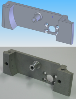
Computer-aided design (CAD) is the use of computers to aid in the creation, modification, analysis, or optimization of a design. CAD software is used to increase the productivity of the designer, improve the quality of design, improve communications through documentation, and to create a database for manufacturing. CAD output is often in the form of electronic files for print, machining, or other manufacturing operations. The term CADD is also used.
Mastercam is a suite of Computer-Aided Manufacturing (CAM) and CAD/CAM software applications. Founded in MA in 1983, CNC Software, Inc. is one of the oldest developers of PC-based computer-aided design / computer-aided manufacturing (CAD/CAM) software. They are one of the first to introduce CAD/CAM software designed for both machinists and engineers. Mastercam, CNC Software’s main product, started as a 2D CAM system with CAD tools that let machinists design virtual parts on a computer screen and also guided computer numerical controlled (CNC) machine tools in the manufacture of parts. Since then, Mastercam has grown into the most widely used CAD/CAM package in the world. CNC Software, Inc. is now located in Tolland, Connecticut.
Creo Elements/Pro, formerly known as Pro/ENGINEER and Wildfire, is a 3D CAD, CAM, CAE, and associative solid modelling app. It is one of a suite of 10 collaborative applications that provide solid modelling, assembly modelling, 2D orthographic views, finite element analysis, direct and parametric modelling, sub-divisional and NURBS surface modelling, and NC and tooling functionality for mechanical designers. Creo Elements/Parametric compete directly with Solidworks, CATIA, and NX/Solid Edge. It was created by Parametric Technology Corporation (PTC) and was the first of its kind to market.
CAD data exchange is a modality of data exchange used to translate data between different Computer-aided design (CAD) authoring systems or between CAD and other downstream CAx systems.
Manufacturing process management (MPM) is a collection of technologies and methods used to define how products are to be manufactured. MPM differs from ERP/MRP which is used to plan the ordering of materials and other resources, set manufacturing schedules, and compile cost data.

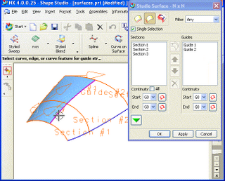
Rhinoceros is a commercial 3D computer graphics and computer-aided design (CAD) application software developed by Robert McNeel & Associates, an American, privately held, employee-owned company founded in 1980. Rhinoceros geometry is based on the NURBS mathematical model, which focuses on producing mathematically precise representation of curves and freeform surfaces in computer graphics.
Incremental sheet forming is a sheet metal forming technique where a sheet is formed into the final workpiece by a series of small incremental deformations. However, studies have shown that it can be applied to polymer and composite sheets too. Generally, the sheet is formed by a round tipped tool, typically 5 to 20mm in diameter. The tool, which can be attached to a CNC machine, a robot arm or similar, indents into the sheet by about 1 mm and follows a contour for the desired part. It then indents further and draws the next contour for the part into the sheet and continues to do this until the full part is formed. ISF can be divided into variants depending on the number of contact points between tool, sheet and die. The term Single Point Incremental Forming (SPIF) is used when the opposite side of the sheet is supported by a faceplate and Two Point Incremental Forming (TPIF) when a full or partial die supports the sheet.

Rapid prototyping is a group of techniques used to quickly fabricate a scale model of a physical part or assembly using three-dimensional computer aided design (CAD) data. Construction of the part or assembly is usually done using 3D printing or "additive layer manufacturing" technology.
The term "feature" implies different meanings in different engineering disciplines. This has resulted in many ambiguous definitions for feature. A feature, in computer-aided design (CAD), usually refers to a region of a part with some interesting geometric or topological properties. These are more precisely called form features. Form features contain both shape information and parametric information of a region of interest. They are now ubiquitous in most current CAD software, where they are used as the primary means of creating 3D geometric models. Examples of form features are extruded boss, loft, etc. Form feature is not the only type of feature that is discussed in CAD literature. Sometimes a part's functional or manufacturing features of the subject of attention. Although it is quite possible to see form features and manufacturing features are called by the same name, they are not exactly the same concepts. For example, one may either use the name "pocket" to refer to a swept cut on the boundary of a part model, or to refer to a trace left on the part boundary by a specific machining operation. The former is exclusively concerned with a geometric shape whereas the latter is concerned with both the geometric shape and a manufacturing operation, needing more parameters in its definition. As such, a manufacturing feature can be minimally defined as a form feature, but not necessarily vice versa. Machining features are an important subset of manufacturing features. A machining feature can be regarded as the volume swept by a "cutting" tool, which is always a negative (subtracted) volume. Finally, there is also the concept of assembly feature, which encodes the assembly method between connected components.

STEP-NC is a machine tool control language that extends the ISO 10303 STEP standards with the machining model in ISO 14649, adding geometric dimension and tolerance data for inspection, and the STEP PDM model for integration into the wider enterprise. The combined result has been standardized as ISO 10303-238.
BobCAD-CAM is a developer of CAD/CAM software for the CNC metalworking and manufacturing industry. Based in Clearwater, FL, BobCAD-CAM has a staff of approximately 85 employees. Since opening in 1985 they've developed a reputation in the industry as having one of the most powerful and affordable CAD-CAM software available.
Electron-beam freeform fabrication (EBF3) is an additive manufacturing process that builds near-net-shape parts requiring less raw material and finish machining than traditional manufacturing methods. It uses a focused electron beam in a vacuum environment to create a molten pool on a metallic substrate.

WorkNC is a Computer aided manufacturing (CAM) software developed by Sescoi for multi-axis machining.

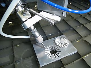
Milling is the process of machining using rotary cutters to remove material by advancing a cutter into a workpiece. This may be done varying direction on one or several axes, cutter head speed, and pressure. Milling covers a wide variety of different operations and machines, on scales from small individual parts to large, heavy-duty gang milling operations. It is one of the most commonly used processes for machining custom parts to precise tolerances.

CNC plunge milling, also called z-axis milling, is a CNC milling process. In this process, the feed is provided linearly along the tool axis while doing CNC processing.
Virtual machining is the practice of using computers to simulate and model the use of machine tools for part manufacturing. Such activity replicates the behavior and errors of a real environment in virtual reality systems. This can provide useful ways to manufacture products without physical testing on the shop floor. As a result, time and cost of part production can be decreased.
Design for additive manufacturing is design for manufacturability as applied to additive manufacturing (AM). It is a general type of design methods or tools whereby functional performance and/or other key product life-cycle considerations such as manufacturability, reliability, and cost can be optimized subjected to the capabilities of additive manufacturing technologies.

NCSIMUL is a software program developed by the company SPRING Technologies, that is used for simulating, verifying, and optimizing CNC machining in a 3-step process. It reads the post-processed G-code to identify the tool path, and replicates the material removal process of the machine by cutting volumes. It then identifies all syntax errors in the code, crashes in the machining environment, and deviations from the modeled CAD part.