
A computer program is a sequence or set of instructions in a programming language for a computer to execute. It is one component of software, which also includes documentation and other intangible components.

A programmable logic controller (PLC) or programmable controller is an industrial computer that has been ruggedized and adapted for the control of manufacturing processes, such as assembly lines, machines, robotic devices, or any activity that requires high reliability, ease of programming, and process fault diagnosis.
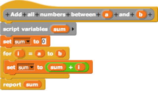
In computing, a visual programming language, also known as diagrammatic programming, graphical programming or block coding, is a programming language that lets users create programs by manipulating program elements graphically rather than by specifying them textually. A VPL allows programming with visual expressions, spatial arrangements of text and graphic symbols, used either as elements of syntax or secondary notation. For example, many VPLs are based on the idea of "boxes and arrows", where boxes or other screen objects are treated as entities, connected by arrows, lines or arcs which represent relations. VPLs are generally the basis of Low-code development platforms.

A flowchart is a type of diagram that represents a workflow or process. A flowchart can also be defined as a diagrammatic representation of an algorithm, a step-by-step approach to solving a task.

In systems engineering, information systems and software engineering, the systems development life cycle (SDLC), also referred to as the application development life cycle, is a process for planning, creating, testing, and deploying an information system. The SDLC concept applies to a range of hardware and software configurations, as a system can be composed of hardware only, software only, or a combination of both. There are usually six stages in this cycle: requirement analysis, design, development and testing, implementation, documentation, and evaluation.

Business process modeling (BPM) is the action of capturing and representing processes of an enterprise, so that the current business processes may be analyzed, applied securely and consistently, improved, and automated.
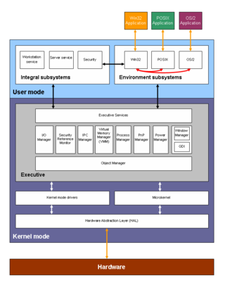
A block diagram is a diagram of a system in which the principal parts or functions are represented by blocks connected by lines that show the relationships of the blocks. They are heavily used in engineering in hardware design, electronic design, software design, and process flow diagrams.
A data-flow diagram is a way of representing a flow of data through a process or a system. The DFD also provides information about the outputs and inputs of each entity and the process itself. A data-flow diagram has no control flow — there are no decision rules and no loops. Specific operations based on the data can be represented by a flowchart.

Flow diagram is a diagram representing a flow or set of dynamic relationships in a system. The term flow diagram is also used as a synonym for flowchart, and sometimes as a counterpart of the flowchart.
The term conceptual model refers to any model that is formed after a conceptualization or generalization process. Conceptual models are often abstractions of things in the real world, whether physical or social. Semantic studies are relevant to various stages of concept formation. Semantics is fundamentally a study of concepts, the meaning that thinking beings give to various elements of their experience.
Object-oriented analysis and design (OOAD) is a technical approach for analyzing and designing an application, system, or business by applying object-oriented programming, as well as using visual modeling throughout the software development process to guide stakeholder communication and product quality.
Glossary of Unified Modeling Language (UML) terms provides a compilation of terminology used in all versions of UML, along with their definitions. Any notable distinctions that may exist between versions are noted with the individual entry it applies to.

In software engineering, structured analysis (SA) and structured design (SD) are methods for analyzing business requirements and developing specifications for converting practices into computer programs, hardware configurations, and related manual procedures.
A signal-flow graph or signal-flowgraph (SFG), invented by Claude Shannon, but often called a Mason graph after Samuel Jefferson Mason who coined the term, is a specialized flow graph, a directed graph in which nodes represent system variables, and branches represent functional connections between pairs of nodes. Thus, signal-flow graph theory builds on that of directed graphs, which includes as well that of oriented graphs. This mathematical theory of digraphs exists, of course, quite apart from its applications.

In systems engineering, software engineering, and computer science, a function model or functional model is a structured representation of the functions within the modeled system or subject area.

A functional flow block diagram (FFBD) is a multi-tier, time-sequenced, step-by-step flow diagram of a system's functional flow. The term "functional" in this context is different from its use in functional programming or in mathematics, where pairing "functional" with "flow" would be ambiguous. Here, "functional flow" pertains to the sequencing of operations, with "flow" arrows expressing dependence on the success of prior operations. FFBDs may also express input and output data dependencies between functional blocks, as shown in figures below, but FFBDs primarily focus on sequencing.
Systems modeling or system modeling is the interdisciplinary study of the use of models to conceptualize and construct systems in business and IT development.
Node graph architecture is a software design structured around the notion of a node graph. Both the source code and the user interface are designed around the editing and composition of atomic functional units. Node graphs are a type of visual programming language.
UML is a modeling language used by software developers. UML can be used to develop diagrams and provide users (programmers) with ready-to-use, expressive modeling examples. Some UML tools generate program language code from UML. UML can be used for modeling a system independent of a platform language. UML is a graphical language for visualizing, specifying, constructing, and documenting information about software-intensive systems. UML gives a standard way to write a system model, covering conceptual ideas. With an understanding of modeling, the use and application of UML can make the software development process more efficient.
A function analysis diagram (FAD) is a method used in engineering design to model and visualize the functions and interactions between components of a system or product. It represents the functional relationships through a diagram consisting of blocks, which represent physical components, and labeled relations/arrows between them, which represent useful or harmful functional interactions.
