
A cathode-ray tube (CRT) is a vacuum tube containing one or more electron guns, which emit electron beams that are manipulated to display images on a phosphorescent screen. The images may represent electrical waveforms on an oscilloscope, a frame of video on an analog television set (TV), digital raster graphics on a computer monitor, or other phenomena like radar targets. A CRT in a TV is commonly called a picture tube. CRTs have also been used as memory devices, in which case the screen is not intended to be visible to an observer. The term cathode ray was used to describe electron beams when they were first discovered, before it was understood that what was emitted from the cathode was a beam of electrons.

Diffraction is the deviation of waves from straight-line propagation due to an obstacle or through an aperture. The diffracting object or aperture effectively becomes a secondary source of the propagating wave. Diffraction is the same physical effect as interference, but interference is typically applied to superposition of a few waves and the term diffraction is used when many waves are superposed.

The photoelectric effect is the emission of electrons from a material caused by electromagnetic radiation such as ultraviolet light. Electrons emitted in this manner are called photoelectrons. The phenomenon is studied in condensed matter physics, solid state, and quantum chemistry to draw inferences about the properties of atoms, molecules and solids. The effect has found use in electronic devices specialized for light detection and precisely timed electron emission.

An X-ray (also known in many languages as Röntgen radiation) is a form of high-energy electromagnetic radiation with a wavelength shorter than those of ultraviolet rays and longer than those of gamma rays. Roughly, X-rays have a wavelength ranging from 10 nanometers to 10 picometers, corresponding to frequencies in the range of 30 petahertz to 30 exahertz (3×10¹⁶ Hz to 3×10¹⁹ Hz) and photon energies in the range of 100 eV to 100 keV, respectively.
In physics, attenuation is the gradual loss of flux intensity through a medium. For instance, dark glasses attenuate sunlight, lead attenuates X-rays, and water and air attenuate both light and sound at variable attenuation rates.
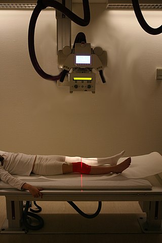
Radiography is an imaging technique using X-rays, gamma rays, or similar ionizing radiation and non-ionizing radiation to view the internal form of an object. Applications of radiography include medical and industrial radiography. Similar techniques are used in airport security,. To create an image in conventional radiography, a beam of X-rays is produced by an X-ray generator and it is projected towards the object. A certain amount of the X-rays or other radiation are absorbed by the object, dependent on the object's density and structural composition. The X-rays that pass through the object are captured behind the object by a detector. The generation of flat two-dimensional images by this technique is called projectional radiography. In computed tomography, an X-ray source and its associated detectors rotate around the subject, which itself moves through the conical X-ray beam produced. Any given point within the subject is crossed from many directions by many different beams at different times. Information regarding the attenuation of these beams is collated and subjected to computation to generate two-dimensional images on three planes which can be further processed to produce a three-dimensional image.

External beam radiation therapy (EBRT) is a form of radiotherapy that utilizes a high-energy collimated beam of ionizing radiation, from a source outside the body, to target and kill cancer cells. A radiotherapy beam is composed of particles which travel in a consistent direction; each radiotherapy beam consists of one type of particle intended for use in treatment, though most beams contain some contamination by other particle types.
Optics is the branch of physics which involves the behavior and properties of light, including its interactions with matter and the construction of instruments that use or detect it. Optics usually describes the behavior of visible, ultraviolet, and infrared light. Because light is an electromagnetic wave, other forms of electromagnetic radiation such as X-rays, microwaves, and radio waves exhibit similar properties.

A synchrotron light source is a source of electromagnetic radiation (EM) usually produced by a storage ring, for scientific and technical purposes. First observed in synchrotrons, synchrotron light is now produced by storage rings and other specialized particle accelerators, typically accelerating electrons. Once the high-energy electron beam has been generated, it is directed into auxiliary components such as bending magnets and insertion devices in storage rings and free electron lasers. These supply the strong magnetic fields perpendicular to the beam that are needed to stimulate the high energy electrons to emit photons.

An X-ray tube is a vacuum tube that converts electrical input power into X-rays. The availability of this controllable source of X-rays created the field of radiography, the imaging of partly opaque objects with penetrating radiation. In contrast to other sources of ionizing radiation, X-rays are only produced as long as the X-ray tube is energized. X-ray tubes are also used in CT scanners, airport luggage scanners, X-ray crystallography, material and structure analysis, and for industrial inspection.

X-ray spectroscopy is a general term for several spectroscopic techniques for characterization of materials by using x-ray radiation.

A Crookes tube is an early experimental discharge tube with partial vacuum invented by English physicist William Crookes and others around 1869–1875, in which cathode rays, streams of electrons, were discovered.
An X-ray image intensifier (XRII) is an image intensifier that converts X-rays into visible light at higher intensity than the more traditional fluorescent screens can. Such intensifiers are used in X-ray imaging systems to allow low-intensity X-rays to be converted to a conveniently bright visible light output. The device contains a low absorbency/scatter input window, typically aluminum, input fluorescent screen, photocathode, electron optics, output fluorescent screen and output window. These parts are all mounted in a high vacuum environment within glass or, more recently, metal/ceramic. By its intensifying effect, It allows the viewer to more easily see the structure of the object being imaged than fluorescent screens alone, whose images are dim. The XRII requires lower absorbed doses due to more efficient conversion of X-ray quanta to visible light. This device was originally introduced in 1948.
X-ray optics is the branch of optics dealing with X-rays, rather than visible light. It deals with focusing and other ways of manipulating the X-ray beams for research techniques such as X-ray diffraction, X-ray crystallography, X-ray fluorescence, small-angle X-ray scattering, X-ray microscopy, X-ray phase-contrast imaging, and X-ray astronomy.
Peak kilovoltage (kVp) refers to the maximum high voltage applied across an X-ray tube to produce the X-rays. During X-ray generation, surface electrons are released from a heated cathode by thermionic emission. The applied voltage (kV) accelerates these electrons toward an anode target, ultimately producing X-rays when the electrons are stopped in the anode. Thus, the kVp corresponds to the highest kinetic energy of the electrons striking the target, and is proportional to the maximum photon energy of the resulting X-ray emission spectrum. In early and basic X-ray equipment, the applied voltage varies cyclically, with one, two, or more pulses per mains AC power cycle. One standard way to measure pulsating DC is its peak amplitude, hence kVp. Most modern X-ray generators apply a constant potential across the X-ray tube; in such systems, the kVp and the steady-state kV are identical.
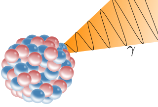
A gamma ray, also known as gamma radiation (symbol
γ
), is a penetrating form of electromagnetic radiation arising from the radioactive decay of atomic nuclei. It consists of the shortest wavelength electromagnetic waves, typically shorter than those of X-rays. With frequencies above 30 exahertz (3×10¹⁹ Hz) and wavelengths less than 10 picometers (1×10⁻¹¹ m), gamma ray photons have the highest photon energy of any form of electromagnetic radiation. Paul Villard, a French chemist and physicist, discovered gamma radiation in 1900 while studying radiation emitted by radium. In 1903, Ernest Rutherford named this radiation gamma rays based on their relatively strong penetration of matter; in 1900, he had already named two less penetrating types of decay radiation (discovered by Henri Becquerel) alpha rays and beta rays in ascending order of penetrating power.
An X-ray filter is a device placed in front of an X-ray source in order to reduce the intensity of particular wavelengths from its spectrum and selectively alter the distribution of X-ray wavelengths within a given beam before reaching the image receptor. Adding a filtration device to certain x-ray examinations attenuates the x-ray beam by eliminating lower energy x-ray photons to produce a clearer image with greater anatomic detail to better visualize differences in tissue densities. While a compensating filter provides a better radiographic image by removing lower energy photons, it also reduces radiation dose to the patient.
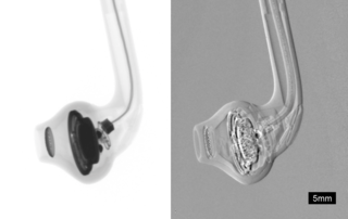
Phase-contrast X-ray imaging or phase-sensitive X-ray imaging is a general term for different technical methods that use information concerning changes in the phase of an X-ray beam that passes through an object in order to create its images. Standard X-ray imaging techniques like radiography or computed tomography (CT) rely on a decrease of the X-ray beam's intensity (attenuation) when traversing the sample, which can be measured directly with the assistance of an X-ray detector. However, in phase contrast X-ray imaging, the beam's phase shift caused by the sample is not measured directly, but is transformed into variations in intensity, which then can be recorded by the detector.

X-ray emission spectroscopy (XES) is a form of X-ray spectroscopy in which a core electron is excited by an incident x-ray photon and then this excited state decays by emitting an x-ray photon to fill the core hole. The energy of the emitted photon is the energy difference between the involved electronic levels. The analysis of the energy dependence of the emitted photons is the aim of the X-ray emission spectroscopy.
