Digital image processing is the use of a digital computer to process digital images through an algorithm. As a subcategory or field of digital signal processing, digital image processing has many advantages over analog image processing. It allows a much wider range of algorithms to be applied to the input data and can avoid problems such as the build-up of noise and distortion during processing. Since images are defined over two dimensions digital image processing may be modeled in the form of multidimensional systems. The generation and development of digital image processing are mainly affected by three factors: first, the development of computers; second, the development of mathematics ; third, the demand for a wide range of applications in environment, agriculture, military, industry and medical science has increased.

Isometric projection is a method for visually representing three-dimensional objects in two dimensions in technical and engineering drawings. It is an axonometric projection in which the three coordinate axes appear equally foreshortened and the angle between any two of them is 120 degrees.

A 3D projection is a design technique used to display a three-dimensional (3D) object on a two-dimensional (2D) surface. These projections rely on visual perspective and aspect analysis to project a complex object for viewing capability on a simpler plane.
The scale-invariant feature transform (SIFT) is a computer vision algorithm to detect, describe, and match local features in images, invented by David Lowe in 1999. Applications include object recognition, robotic mapping and navigation, image stitching, 3D modeling, gesture recognition, video tracking, individual identification of wildlife and match moving.

Image stitching or photo stitching is the process of combining multiple photographic images with overlapping fields of view to produce a segmented panorama or high-resolution image. Commonly performed through the use of computer software, most approaches to image stitching require nearly exact overlaps between images and identical exposures to produce seamless results, although some stitching algorithms actually benefit from differently exposed images by doing high-dynamic-range imaging in regions of overlap. Some digital cameras can stitch their photos internally.
In computer vision, the Lucas–Kanade method is a widely used differential method for optical flow estimation developed by Bruce D. Lucas and Takeo Kanade. It assumes that the flow is essentially constant in a local neighbourhood of the pixel under consideration, and solves the basic optical flow equations for all the pixels in that neighbourhood, by the least squares criterion.
In computer vision, the fundamental matrix is a 3×3 matrix which relates corresponding points in stereo images. In epipolar geometry, with homogeneous image coordinates, x and x′, of corresponding points in a stereo image pair, Fx describes a line on which the corresponding point x′ on the other image must lie. That means, for all pairs of corresponding points holds
The following outline is provided as an overview of and topical guide to computer vision:
Camera resectioning is the process of estimating the parameters of a pinhole camera model approximating the camera that produced a given photograph or video; it determines which incoming light ray is associated with each pixel on the resulting image. Basically, the process determines the pose of the pinhole camera.

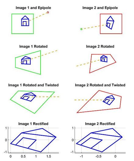
Epipolar geometry is the geometry of stereo vision. When two cameras view a 3D scene from two distinct positions, there are a number of geometric relations between the 3D points and their projections onto the 2D images that lead to constraints between the image points. These relations are derived based on the assumption that the cameras can be approximated by the pinhole camera model.
Binocular disparity refers to the difference in image location of an object seen by the left and right eyes, resulting from the eyes' horizontal separation (parallax). The mind uses binocular disparity to extract depth information from the two-dimensional retinal images in stereopsis. In computer vision, binocular disparity refers to the difference in coordinates of similar features within two stereo images.

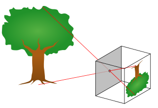
The pinhole camera model describes the mathematical relationship between the coordinates of a point in three-dimensional space and its projection onto the image plane of an ideal pinhole camera, where the camera aperture is described as a point and no lenses are used to focus light. The model does not include, for example, geometric distortions or blurring of unfocused objects caused by lenses and finite sized apertures. It also does not take into account that most practical cameras have only discrete image coordinates. This means that the pinhole camera model can only be used as a first order approximation of the mapping from a 3D scene to a 2D image. Its validity depends on the quality of the camera and, in general, decreases from the center of the image to the edges as lens distortion effects increase.
In computer vision, maximally stable extremal regions (MSER) technique is used as a method of blob detection in images. This technique was proposed by Matas et al. to find correspondences between image elements taken from two images with different viewpoints. This method of extracting a comprehensive number of corresponding image elements contributes to the wide-baseline matching, and it has led to better stereo matching and object recognition algorithms.
Camera auto-calibration is the process of determining internal camera parameters directly from multiple uncalibrated images of unstructured scenes. In contrast to classic camera calibration, auto-calibration does not require any special calibration objects in the scene. In the visual effects industry, camera auto-calibration is often part of the "Match Moving" process where a synthetic camera trajectory and intrinsic projection model are solved to reproject synthetic content into video.
Computer stereo vision is the extraction of 3D information from digital images, such as those obtained by a CCD camera. By comparing information about a scene from two vantage points, 3D information can be extracted by examining the relative positions of objects in the two panels. This is similar to the biological process of stereopsis.
Document mosaicing is a process that stitches multiple, overlapping snapshot images of a document together to produce one large, high resolution composite. The document is slid under a stationary, over-the-desk camera by hand until all parts of the document are snapshotted by the camera's field of view. As the document slid under the camera, all motion of the document is coarsely tracked by the vision system. The document is periodically snapshotted such that the successive snapshots are overlap by about 50%. The system then finds the overlapped pairs and stitches them together repeatedly until all pairs are stitched together as one piece of document.

3D reconstruction from multiple images is the creation of three-dimensional models from a set of images. It is the reverse process of obtaining 2D images from 3D scenes.

In the field of computer vision, any two images of the same planar surface in space are related by a homography. This has many practical applications, such as image rectification, image registration, or camera motion—rotation and translation—between two images. Once camera resectioning has been done from an estimated homography matrix, this information may be used for navigation, or to insert models of 3D objects into an image or video, so that they are rendered with the correct perspective and appear to have been part of the original scene.
Chessboards arise frequently in computer vision theory and practice because their highly structured geometry is well-suited for algorithmic detection and processing. The appearance of chessboards in computer vision can be divided into two main areas: camera calibration and feature extraction. This article provides a unified discussion of the role that chessboards play in the canonical methods from these two areas, including references to the seminal literature, examples, and pointers to software implementations.
In computer vision, rigid motion segmentation is the process of separating regions, features, or trajectories from a video sequence into coherent subsets of space and time. These subsets correspond to independent rigidly moving objects in the scene. The goal of this segmentation is to differentiate and extract the meaningful rigid motion from the background and analyze it. Image segmentation techniques labels the pixels to be a part of pixels with certain characteristics at a particular time. Here, the pixels are segmented depending on its relative movement over a period of time i.e. the time of the video sequence.


