Related Research Articles

In physics, electromagnetic radiation refers to the waves of the electromagnetic field, propagating (radiating) through space, carrying electromagnetic radiant energy. It includes radio waves, microwaves, infrared, (visible) light, ultraviolet, X-rays, and gamma rays.
The electromagnetic spectrum is the range of frequencies of electromagnetic radiation and their respective wavelengths and photon energies.

Microwave is a form of electromagnetic radiation with wavelengths ranging from about one meter to one millimeter; with frequencies between 300 MHz (1 m) and 300 GHz (1 mm). Different sources define different frequency ranges as microwaves; the above broad definition includes both UHF and EHF bands. A more common definition in radio-frequency engineering is the range between 1 and 100 GHz. In all cases, microwaves include the entire SHF band at minimum. Frequencies in the microwave range are often referred to by their IEEE radar band designations: S, C, X, Ku, K, or Ka band, or by similar NATO or EU designations.
In telecommunication, the free-space path loss (FSPL) is the attenuation of radio energy between the feedpoints of two antennas that results from the combination of the receiving antenna's capture area plus the obstacle-free, line-of-sight path through free space. The "Standard Definitions of Terms for Antennas", IEEE Std 145-1993, defines "free-space loss" as "The loss between two isotropic radiators in free space, expressed as a power ratio." It does not include any power loss in the antennas themselves due to imperfections such as resistance. Free space loss increases with the square of distance between the antennas because the radio waves spread out by the inverse square law and decreases with the square of the wavelength of the radio waves. The FSPL is rarely used standalone, but rather as a part of the Friis transmission formula, which includes the gain of antennas. It is a factor that must be included in the power link budget of a radio communication system, to ensure that sufficient radio power reaches the receiver such that the transmitted signal is received intelligibly.

A Fresnel zone, named after physicist Augustin-Jean Fresnel, is one of a series of confocal prolate ellipsoidal regions of space between and around a transmitter and a receiver. Transmitted radio, sound, or light waves can follow slightly different paths before reaching a receiver, especially if there are obstructions or reflecting objects between the two. The waves can arrive at slightly different times and will be slightly out of phase due to the different path lengths. Depending on the magnitude of the phase shift, the waves can interfere constructively or destructively. The size of the calculated Fresnel zone at any particular distance from the transmitter and receiver can help to predict whether obstructions or discontinuities along the path will cause significant interference.
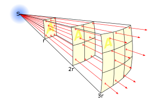
In science, an inverse-square law is any scientific law stating that a specified physical quantity is inversely proportional to the square of the distance from the source of that physical quantity. The fundamental cause for this can be understood as geometric dilution corresponding to point-source radiation into three-dimensional space.

Radio waves are a type of electromagnetic radiation with wavelengths in the electromagnetic spectrum longer than infrared light. Radio waves have frequencies as high as 300 gigahertz (GHz) to as low as 30 hertz (Hz). At 300 GHz, the corresponding wavelength is 1 mm ; at 30 Hz the corresponding wavelength is 10,000 km. Like all other electromagnetic waves, radio waves travel at the speed of light in vacuum. Radio waves are generated by charged particles undergoing acceleration, such as time-varying electric currents. Naturally occurring radio waves are emitted by lightning and astronomical objects.
Low frequency (LF) is the ITU designation for radio frequencies (RF) in the range of 30–300 kHz. Since its wavelengths range from 10–1 km, respectively, it is also known as the kilometre band or kilometre wave.

In radio engineering, an antenna or aerial is the interface between radio waves propagating through space and electric currents moving in metal conductors, used with a transmitter or receiver. In transmission, a radio transmitter supplies an electric current to the antenna's terminals, and the antenna radiates the energy from the current as electromagnetic waves. In reception, an antenna intercepts some of the power of a radio wave in order to produce an electric current at its terminals, that is applied to a receiver to be amplified. Antennas are essential components of all radio equipment.
In physics, a virtual particle is a transient quantum fluctuation that exhibits some of the characteristics of an ordinary particle, while having its existence limited by the uncertainty principle. The concept of virtual particles arises in perturbation theory of quantum field theory where interactions between ordinary particles are described in terms of exchanges of virtual particles. A process involving virtual particles can be described by a schematic representation known as a Feynman diagram, in which virtual particles are represented by internal lines.

A parabolic antenna is an antenna that uses a parabolic reflector, a curved surface with the cross-sectional shape of a parabola, to direct the radio waves. The most common form is shaped like a dish and is popularly called a dish antenna or parabolic dish. The main advantage of a parabolic antenna is that it has high directivity. It functions similarly to a searchlight or flashlight reflector to direct the radio waves in a narrow beam, or receive radio waves from one particular direction only. Parabolic antennas have some of the highest gains, meaning that they can produce the narrowest beamwidths, of any antenna type. In order to achieve narrow beamwidths, the parabolic reflector must be much larger than the wavelength of the radio waves used, so parabolic antennas are used in the high frequency part of the radio spectrum, at UHF and microwave (SHF) frequencies, at which the wavelengths are small enough that conveniently-sized reflectors can be used.

The near field and far field are regions of the electromagnetic field (EM) around an object, such as a transmitting antenna, or the result of radiation scattering off an object. Non-radiative 'near-field' behaviors dominate close to the antenna or scattering object, while electromagnetic radiation 'far-field' behaviors dominate at greater distances.

Extremely low frequency (ELF) is the ITU designation for electromagnetic radiation with frequencies from 3 to 30 Hz, and corresponding wavelengths of 100,000 to 10,000 kilometers, respectively. In atmospheric science, an alternative definition is usually given, from 3 Hz to 3 kHz. In the related magnetosphere science, the lower frequency electromagnetic oscillations are considered to lay in the ULF range, which is thus also defined differently from the ITU radio bands.

In radio and telecommunications a dipole antenna or doublet is the simplest and most widely used class of antenna. The dipole is any one of a class of antennas producing a radiation pattern approximating that of an elementary electric dipole with a radiating structure supporting a line current so energized that the current has only one node at each end. A dipole antenna commonly consists of two identical conductive elements such as metal wires or rods. The driving current from the transmitter is applied, or for receiving antennas the output signal to the receiver is taken, between the two halves of the antenna. Each side of the feedline to the transmitter or receiver is connected to one of the conductors. This contrasts with a monopole antenna, which consists of a single rod or conductor with one side of the feedline connected to it, and the other side connected to some type of ground. A common example of a dipole is the "rabbit ears" television antenna found on broadcast television sets.

A zone plate is a device used to focus light or other things exhibiting wave character. Unlike lenses or curved mirrors, zone plates use diffraction instead of refraction or reflection. Based on analysis by French physicist Augustin-Jean Fresnel, they are sometimes called Fresnel zone plates in his honor. The zone plate's focusing ability is an extension of the Arago spot phenomenon caused by diffraction from an opaque disc.
A link budget is an accounting of all of the power gains and losses that a communication signal experiences in a telecommunication system; from a transmitter, through a medium to the receiver. It is an equation giving the received power from the transmitter power, after the attenuation of the transmitted signal due to propagation, as well as the antenna gains and feedline and other losses, and amplification of the signal in the receiver or any repeaters it passes through. A link budget is a design aid, calculated during the design of a communication system to determine the received power, to ensure that the information is received intelligibly with an adequate signal-to-noise ratio. Randomly varying channel gains such as fading are taken into account by adding some margin depending on the anticipated severity of its effects. The amount of margin required can be reduced by the use of mitigating techniques such as antenna diversity or frequency hopping.
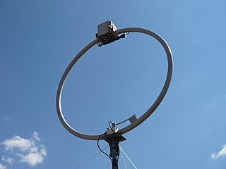
A loop antenna is a radio antenna consisting of a loop or coil of wire, tubing, or other electrical conductor usually fed by a balanced source or feeding a balanced load. Within this physical description there are two distinct antenna types:
Non-line-of-sight (NLOS) radio propagation occurs outside of the typical line of sight (LOS) between the transmitter and receiver, such as in ground reflections. Near-line-of-sight conditions refer to partial obstruction by a physical object present in the innermost Fresnel zone.
Near vertical incidence skywave, or NVIS, is a skywave radio-wave propagation path that provides usable signals in the distances range — usually 0–650 km (0–400 miles). It is used for military and paramilitary communications, broadcasting, especially in the tropics, and by radio amateurs for nearby contacts circumventing line-of-sight barriers. The radio waves travel near-vertically upwards into the ionosphere, where they are refracted back down and can be received within a circular region up to 650 km from the transmitter. If the frequency is too high, refraction fails to occur and if it is too low, absorption in the ionospheric D layer may reduce the signal strength.
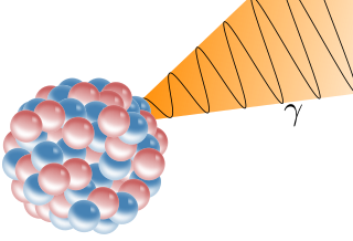
A gamma ray, or gamma radiation, is a penetrating form of electromagnetic radiation arising from the radioactive decay of atomic nuclei. It consists of the shortest wavelength electromagnetic waves and so imparts the highest photon energy. Paul Villard, a French chemist and physicist, discovered gamma radiation in 1900 while studying radiation emitted by radium. In 1903, Ernest Rutherford named this radiation gamma rays based on their relatively strong penetration of matter; in 1900 he had already named two less penetrating types of decay radiation alpha rays and beta rays in ascending order of penetrating power.
References
- ↑ "TN-261 — Safety Code 6 (SC6) Radio Frequency Exposure Compliance Evaluation Template (Uncontrolled Environment Exposure Limits)". www.ic.gc.ca. 2015-03-19. Retrieved 2019-06-30.
![]()
| This article related to radio communications is a stub. You can help Wikipedia by expanding it. |