
An optical attenuator, or fiber optic attenuator, is a device used to reduce the power level of an optical signal, either in free space or in an optical fiber. The basic types of optical attenuators are fixed, step-wise variable, and continuously variable.
A transmission medium is a system or substance that can mediate the propagation of signals for the purposes of telecommunication. Signals are typically imposed on a wave of some kind suitable for the chosen medium. For example, data can modulate sound, and a transmission medium for sounds may be air, but solids and liquids may also act as the transmission medium. Vacuum or air constitutes a good transmission medium for electromagnetic waves such as light and radio waves. While a material substance is not required for electromagnetic waves to propagate, such waves are usually affected by the transmission media they pass through, for instance, by absorption or reflection or refraction at the interfaces between media. Technical devices can therefore be employed to transmit or guide waves. Thus, an optical fiber or a copper cable is used as transmission media.
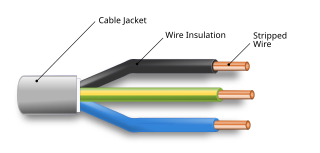
An electrical cable is an assembly of one or more wires running side by side or bundled, which is used as an electrical conductor, i.e., to carry electric current. One or more electrical cables and their corresponding connectors may be formed into a cable assembly, which is not necessarily suitable for connecting two devices but can be a partial product. Cable assemblies can also take the form of a cable tree or cable harness, used to connect many terminals together.

Components of an electrical circuit are electrically connected if an electric current can run between them through an electrical conductor. An electrical connector is an electromechanical device used to create an electrical connection between parts of an electrical circuit, or between different electrical circuits, thereby joining them into a larger circuit. Most electrical connectors have a gender – i.e. the male component, called a plug, connects to the female component, or socket. The connection may be removable, require a tool for assembly and removal, or serve as a permanent electrical joint between two points. An adapter can be used to join dissimilar connectors.

A ferrule is any of a number of types of objects, generally used for fastening, joining, sealing, or reinforcement. They are often narrow circular rings made from metal, or less commonly, plastic. Ferrules are also often referred to as eyelets or grommets within the manufacturing industry.

Electrical wiring is an electrical installation of cabling and associated devices such as switches, distribution boards, sockets, and light fittings in a structure.

Crimping is a method of joining two or more pieces of metal or other ductile material by deforming one or both of them to hold the other. The bend or deformity is called the crimp. Crimping tools are used to create crimps.
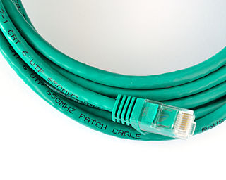
A patch cable, patch cord or patch lead is an electrical or optical cable used to connect one electronic or optical device to another for signal routing. Devices of different types are connected with patch cords.

Twist-on wire connectors are a type of electrical connector used to fasten two or more low-voltage electrical conductors. They are widely used in North America and several European countries in residential, commercial and industrial building power wiring, but have been banned in some other jurisdictions.

Breakout-style fiberoptic cable, is an optical fiber cable containing several jacketed simplex optical fibers packaged together inside an outer jacket. This differs from distribution-style cable, in which tight-buffered fibers are bundled together, with only the outer cable jacket of the cable protecting them. The design of breakout-style cable adds strength for ruggedized drops, however the cable is larger and more expensive than distribution-style cable. Breakout cable is suitable for short riser and plenum applications and also for use in conduits, where a very simple cable run is planned to avoid the use of any splicebox or spliced fiber pigtails.

An optical fiber, or optical fibre in Commonwealth English, is a flexible glass or plastic fiber that can transmit light from one end to the other. Such fibers find wide usage in fiber-optic communications, where they permit transmission over longer distances and at higher bandwidths than electrical cables. Fibers are used instead of metal wires because signals travel along them with less loss and are immune to electromagnetic interference. Fibers are also used for illumination and imaging, and are often wrapped in bundles so they may be used to carry light into, or images out of confined spaces, as in the case of a fiberscope. Specially designed fibers are also used for a variety of other applications, such as fiber optic sensors and fiber lasers.

Fiber-optic communication is a method of transmitting information from one place to another by sending pulses of infrared or visible light through an optical fiber. The light is a form of carrier wave that is modulated to carry information. Fiber is preferred over electrical cabling when high bandwidth, long distance, or immunity to electromagnetic interference is required. This type of communication can transmit voice, video, and telemetry through local area networks or across long distances.

The Western Union splice or Lineman splice is a method of joining electrical cable, developed in the nineteenth century during the introduction of the telegraph and named for the Western Union telegraph company. This method can be used where the cable may be subject to loading stress. The wrapping pattern design causes the join to tighten as the conductors pull against each other.

A fiber-optic cable, also known as an optical-fiber cable, is an assembly similar to an electrical cable but containing one or more optical fibers that are used to carry light. The optical fiber elements are typically individually coated with plastic layers and contained in a protective tube suitable for the environment where the cable is used. Different types of cable are used for optical communication in different applications, for example long-distance telecommunication or providing a high-speed data connection between different parts of a building.
Tinsel wire is a type of electrical wire used for applications that require high mechanical flexibility but low current-carrying capacity. Tinsel wire is commonly used in cords of telephones, handsets, headphones, and small electrical appliances. It is far more resistant to metal fatigue failure than either stranded wire or solid wire.

Electrical or fiber-optic connectors used by U.S. Department of Defense were originally developed in the 1930s for severe aeronautical and tactical service applications, and the Type "AN" (Army-Navy) series set the standard for modern military circular connectors. These connectors, and their evolutionary derivatives, are often called Military Standard, "MIL-STD", or (informally) "MIL-SPEC" or sometimes "MS" connectors. They are now used in aerospace, industrial, marine, and even automotive commercial applications.

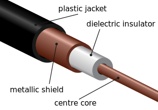
A high-voltage cable is a cable used for electric power transmission at high voltage. A cable includes a conductor and insulation. Cables are considered to be fully insulated. This means that they have a fully rated insulation system that will consist of insulation, semi-con layers, and a metallic shield. This is in contrast to an overhead line, which may include insulation but not fully rated for operating voltage. High-voltage cables of differing types have a variety of applications in instruments, ignition systems, and alternating current (AC) and direct current (DC) power transmission. In all applications, the insulation of the cable must not deteriorate due to the high-voltage stress, ozone produced by electric discharges in air, or tracking. The cable system must prevent contact of the high-voltage conductor with other objects or persons, and must contain and control leakage current. Cable joints and terminals must be designed to control the high-voltage stress to prevent the breakdown of the insulation.
Fujikura Ltd. is a global, Tokyo-based electrical equipment manufacturing company, developing and manufacturing power and telecommunication systems products, including devices for optical fibers, such as cutters and splicers.
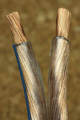
Copper has been used in electrical wiring since the invention of the electromagnet and the telegraph in the 1820s. The invention of the telephone in 1876 created further demand for copper wire as an electrical conductor.


