Western Union splice

Last updated
Figure parts A-D show steps in forming a "short tie" Western Union splice. Figure parts E and F show two possible "long tie" variations. Western Union splice.jpg
Figure parts A–D show steps in forming a "short tie" Western Union splice. Figure parts E and F show two possible "long tie" variations.

The Western Union splice or Lineman splice is a method of joining electrical cable, developed in the nineteenth century during the introduction of the telegraph and named for the Western Union telegraph company. [3] [4] This method can be used where the cable may be subject to loading stress. The wrapping pattern design causes the join to tighten as the conductors pull against each other. [5]

Contents

History

In 1915, Practical electric wiring described it as being, "by far the most widely used splice" in practical electrical wiring work. [1] NASA included the splice in its technical standard Workmanship Standard For Crimping, Interconnecting Cables, Harnesses, And Wiring, first produced in 1998. [6] [4]

Construction

The 1915 textbook Practical Electric Wiring describes the construction of the Western Union splice; short tie and long tie. The short tie splice has it being formed after stripping the insulation from a pair of wires for several inches, each, crossing the wires left over right as shown in figure part A; then, a hooked cross (figure part B) is formed holding the crossing point of the two wires, and pulling the right wire tip toward and pushing the left wire tip away from the worker, leaving the tips oriented vertically as shown. [1] The wires are then held with pliers to the left of their crossing point while the right splice is formed by continuing to wind the wire tip away from the worker, creating 5–6 twists snug against the core wire and against each preceding twist. [1] NASA recommend "tight, with no gaps between adjacent turns". [5] The wires are then again held with pliers, but on the first-made twist, to the right of the crossing point, and then the left splice is formed by winding the remaining wire tip toward the worker for a comparable 5–6 snug twists. [1] The splice wire ends are then trimmed as needed, and the splice may then be soldered, and/or covered (e.g., with a heat-shrunk tube of insulation). [5]

Practical Electric Wiring described the splice as having two variations, the "short tie" (figure part D) and "long tie" (figure parts E or F), with the latter examples having a "twist between wrappings [that] allows a better chance for solder to pass in between the wires". The book suggested the long tie variant more suited to splices where soldering was intended. However, this was not backed up by NASA testing. [1] [7]

Testing

The NASA tests included soldering, and were performed to an organizational standard operating procedure (NASA-STD-8739.3) for a solder termination, which includes a number of specific requirements, including "proper insulation spacing"; tight wrapping; trimming of wire ends to prevent protrusions through the solder; and over-sleeving with a transparent or translucent heat shrink seal to cover the completed splice and all exposed metal. [7]

NASA found both the short and long tie variants to be strong when soldered. The splices were examined in tensile strength ("pull") tests on 16 and 22 American wire gauge wire; even the short tie variation of the Western Union splice performed well after soldering. The test splices never failed at the splice (instead breaking outside of the splice area), leaving NASA to conclude that "the solder connection at the splice was as strong or stronger than the un-spliced wires". [5] [7]

See also

Related Research Articles

<span class="mw-page-title-main">Electrical cable</span> Assembly of one or more wires running side by side or bundled

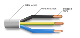
An electrical cable is an assembly of one or more wires running side by side or bundled, which is used as an electrical conductor, i.e., to carry electric current. One or more electrical cables and their corresponding connectors may be formed into a cable assembly, which is not necessarily suitable for connecting two devices but can be a partial product. Cable assemblies can also take the form of a cable tree or cable harness, used to connect many terminals together.

<span class="mw-page-title-main">Wire wrap</span> Electronic component wiring technique

Wire wrap is an electronic component assembly technique that was invented to wire telephone crossbar switches, and later adapted to construct electronic circuit boards. Electronic components mounted on an insulating board are interconnected by lengths of insulated wire run between their terminals, with the connections made by wrapping several turns of uninsulated sections of the wire around a component lead or a socket pin.

<span class="mw-page-title-main">Electrical connector</span> Device used to join electrical conductors

Components of an electrical circuit are electrically connected if an electric current can run between them through an electrical conductor. An electrical connector is an electromechanical device used to create an electrical connection between parts of an electrical circuit, or between different electrical circuits, thereby joining them into a larger circuit. Most electrical connectors have a gender – i.e. the male component, called a plug, connects to the female component, or socket. The connection may be removable, require a tool for assembly and removal, or serve as a permanent electrical joint between two points. An adapter can be used to join dissimilar connectors.

<span class="mw-page-title-main">Electrician</span> Tradesperson specializing in electrical wiring

An electrician is a tradesperson specializing in electrical wiring of buildings, transmission lines, stationary machines, and related equipment. Electricians may be employed in the installation of new electrical components or the maintenance and repair of existing electrical infrastructure. Electricians may also specialize in wiring ships, airplanes, and other mobile platforms, as well as data and cable lines.
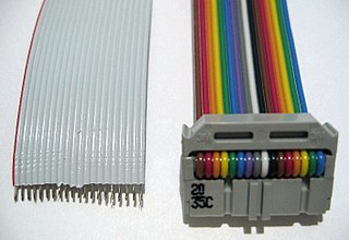
<span class="mw-page-title-main">Electrical wiring</span> Electrical installation of cabling

Electrical wiring is an electrical installation of cabling and associated devices such as switches, distribution boards, sockets, and light fittings in a structure.

<span class="mw-page-title-main">Electrical tape</span> Adhesive electrical insulation

Electrical tape is a type of pressure-sensitive tape used to insulate electrical wires and other materials that conduct electricity. It can be made of many plastics, but PVC is the most popular, as it stretches well and gives effective and long-lasting insulation. Electrical tape for class H insulation is made of fiberglass cloth.

<span class="mw-page-title-main">Crimp (joining)</span> Joining metal workpieces by deforming one or both to hold the other

Crimping is a method of joining two or more pieces of metal or other ductile material by deforming one or both of them to hold the other. The bend or deformity is called the crimp. Crimping tools are used to create crimps.

<span class="mw-page-title-main">Aluminum building wiring</span> Type of electrical wiring

Aluminum building wiring is a type of electrical wiring for residential construction or houses that uses aluminum electrical conductors. Aluminum provides a better conductivity-to-weight ratio than copper, and therefore is also used for wiring power grids, including overhead power transmission lines and local power distribution lines, as well as for power wiring of some airplanes. Utility companies have used aluminum wire for electrical transmission in power grids since around the late 1800s to the early 1900s. It has cost and weight advantages over copper wires. Aluminum in power transmission and distribution applications is still the preferred wire material today.

<span class="mw-page-title-main">Twist-on wire connector</span>

Twist-on wire connectors are a type of electrical connector used to fasten two or more low-voltage electrical conductors. They are widely used in North America and several European countries in residential, commercial and industrial building power wiring, but have been banned in some other jurisdictions.

<span class="mw-page-title-main">Lineman's pliers</span>

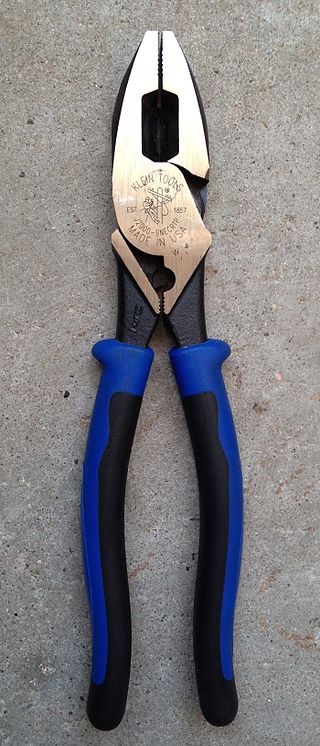
Lineman's pliers, Kleins, linesman pliers, side cutting linesman pliers and combination pliers are a type of pliers used by lineworkers, electricians, and other tradespeople primarily for gripping, twisting, bending and cutting wire, cable, and small metalwork components. They owe their effectiveness to their plier design, which multiplies force through leverage.

<span class="mw-page-title-main">Knob-and-tube wiring</span> Type of electrical wiring

Knob-and-tube wiring is an early standardized method of electrical wiring in buildings, in common use in North America from about 1880 to the 1930s. It consisted of single-insulated copper conductors run within wall or ceiling cavities, passing through joist and stud drill-holes via protective porcelain insulating tubes, and supported along their length on nailed-down porcelain knob insulators. Where conductors entered a wiring device such as a lamp or switch, or were pulled into a wall, they were protected by flexible cloth insulating sleeving called loom. The first insulation was asphalt-saturated cotton cloth, then rubber became common. Wire splices in such installations were twisted together for good mechanical strength, then soldered and wrapped with rubber insulating tape and friction tape, or made inside metal junction boxes.

<span class="mw-page-title-main">Cable harness</span> Bundle of electrical cables or wires

A cable harness, also known as a wire harness, wiring harness, cable assembly, wiring assembly or wiring loom, is an assembly of electrical cables or wires which transmit signals or electrical power. The cables are bound together by a durable material such as rubber, vinyl, electrical tape, conduit, a weave of extruded string, or a combination thereof.

<span class="mw-page-title-main">Modular connector</span> Electrical connector commonly used in telephone and computer networks

A modular connector is a type of electrical connector for cords and cables of electronic devices and appliances, such as in computer networking, telecommunication equipment, and audio headsets.

<span class="mw-page-title-main">Cable lacing</span> Method for tying cables together

Cable lacing is a method for tying wiring harnesses and cable looms, traditionally used in telecommunication, naval, and aerospace applications. This old cable management technique, taught to generations of lineworkers, is still used in some modern applications since it does not create obstructions along the length of the cable, avoiding the handling problems of cables groomed by plastic or hook-and-loop cable ties.

<span class="mw-page-title-main">Screw terminal block</span> Device for electrical wire connection

A screw terminal is a type of electrical connection where a wire is held by the tightening of a screw.

Tinsel wire is a type of electrical wire used for applications that require high mechanical flexibility but low current-carrying capacity. Tinsel wire is commonly used in cords of telephones, handsets, headphones, and small electrical appliances. It is far more resistant to metal fatigue failure than either stranded wire or solid wire.

<span class="mw-page-title-main">Rat-tail splice</span> Method of joining electrical wire

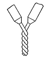
A rat-tail splice, also known as a twist splice or a pig-tail splice, is an electrical splice done with both solid and stranded wire. It’s made with two or more bare wires and wrapping them together symmetrically around the common axis of both wires. The bare splice can be insulated with electrical tape or other means.

<span class="mw-page-title-main">High-voltage cable</span> Cable used for electric power transmission at high voltage

A high-voltage cable is a cable used for electric power transmission at high voltage. A cable includes a conductor and insulation. Cables are considered to be fully insulated. This means that they have a fully rated insulation system that will consist of insulation, semi-con layers, and a metallic shield. This is in contrast to an overhead line, which may include insulation but not fully rated for operating voltage. High-voltage cables of differing types have a variety of applications in instruments, ignition systems, and alternating current (AC) and direct current (DC) power transmission. In all applications, the insulation of the cable must not deteriorate due to the high-voltage stress, ozone produced by electric discharges in air, or tracking. The cable system must prevent contact of the high-voltage conductor with other objects or persons, and must contain and control leakage current. Cable joints and terminals must be designed to control the high-voltage stress to prevent the breakdown of the insulation.

<span class="mw-page-title-main">Copper conductor</span> Electrical wire or other conductor made of copper

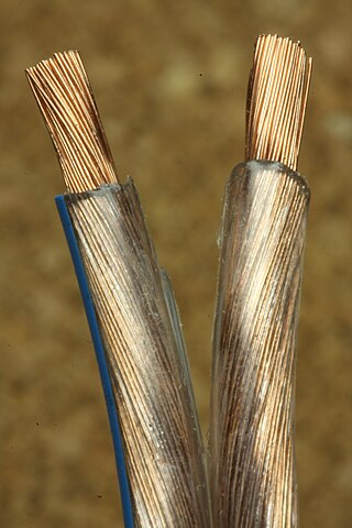
Copper has been used in electrical wiring since the invention of the electromagnet and the telegraph in the 1820s. The invention of the telephone in 1876 created further demand for copper wire as an electrical conductor.

In telecommunications, a line splice is a method of connecting electrical cables or optical fibers.

References

PD-icon.svg This article incorporates public domain material from websites or documents of the National Aeronautics and Space Administration .

  1. 1 2 3 4 5 6 Sharp, John MacLaren (1915). Practical Electric Wiring. New York and London: D. Appleton and Company. pp. 12–14.
  2. Taken from Figures 1 and 2 of [1] and re-labelled.
  3. Lemau (2010-09-26). "Conductor splices". Electrical Engineering Centre. Retrieved 2020-01-22.
  4. 1 2 "How-To: Splice Wire to NASA Standards | Make". Make: DIY Projects and Ideas for Makers. 2012-02-28. Retrieved 2020-01-22.
  5. 1 2 3 4 "Western Union/Lineman Splice". NASA Workmanship Technical Committee. Archived from the original on August 1, 2009.
  6. "Workmanship Standard For Crimping, Interconnecting Cables, Harnesses, And Wiring" (PDF). NASA. 2016 [1998]. p. 71.