
Components of an electrical circuit are electrically connected if an electric current can run between them through an electrical conductor. An electrical connector is an electromechanical device used to create an electrical connection between parts of an electrical circuit, or between different electrical circuits, thereby joining them into a larger circuit.
StarLAN was the first IEEE 802.3 standard for Ethernet over twisted pair wiring. It was standardized by the IEEE Standards Association as 802.3e in 1986, as the 1BASE5 version of Ethernet. The StarLAN Task Force was chaired by Bob Galin.

In telephony, the demarcation point is the point at which the public switched telephone network ends and connects with the customer's on-premises wiring. It is the dividing line which determines who is responsible for installation and maintenance of wiring and equipment—customer/subscriber, or telephone company/provider. The demarcation point varies between countries and has changed over time.

A registered jack (RJ) is a standardized telecommunication network interface for connecting voice and data equipment to a computer service provided by a local exchange carrier or long distance carrier. Registered interfaces were first defined in the Universal Service Ordering Code (USOC) system of the Bell System in the United States for complying with the registration program for customer-supplied telephone equipment mandated by the Federal Communications Commission (FCC) in the 1970s. Subsequently, in 1980 they were codified in title 47 of the Code of Federal Regulations Part 68. Registered jack connections began to see use after their invention in 1973 by Bell Labs. The specification includes physical construction, wiring, and signal semantics. Accordingly, registered jacks are primarily named by the letters RJ, followed by two digits that express the type. Additional letter suffixes indicate minor variations. For example, RJ11, RJ14, and RJ25 are the most commonly used interfaces for telephone connections for one-, two-, and three-line service, respectively. Although these standards are legal definitions in the United States, some interfaces are used worldwide.
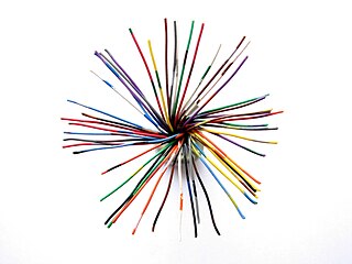
The 25-pair color code, originally known as even-count color code, is a color code used to identify individual conductors in twisted-pair wiring for telecommunications.

A telephone jack and a telephone plug are electrical connectors for connecting a telephone set or other telecommunications apparatus to the telephone wiring inside a building, establishing a connection to a telephone network. The plug is inserted into its counterpart, the jack, which is commonly affixed to a wall or baseboard. The standards for telephone jacks and plugs vary from country to country, though the 6P2C style modular plug has become by far the most common type.

Electrical wiring is an electrical installation of cabling and associated devices such as switches, distribution boards, sockets, and light fittings in a structure.

In telecommunications, structured cabling is building or campus cabling infrastructure that consists of a number of standardized smaller elements called subsystems. Structured cabling components include twisted pair and optical cabling, patch panels and patch cables.

Aluminum building wiring is a type of electrical wiring for residential construction or houses that uses aluminum electrical conductors. Aluminum provides a better conductivity-to-weight ratio than copper, and therefore is also used for wiring power grids, including overhead power transmission lines and local power distribution lines, as well as for power wiring of some airplanes. Utility companies have used aluminum wire for electrical transmission in power grids since around the late 1800s to the early 1900s. It has cost and weight advantages over copper wires. Aluminum in power transmission and distribution applications is still the preferred wire material today.

Twist-on wire connectors are a type of electrical connector used to fasten two or more low-voltage electrical conductors. They are widely used in North America and several European countries in residential, commercial and industrial building power wiring, but have been banned in some other jurisdictions.
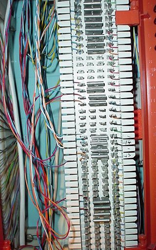
A punch-down block is a type of electrical connection often used in telephony. It is named because the solid copper wires are "punched down" into short open-ended slots which are a type of insulation-displacement connector. These slots, usually cut crosswise across an insulating plastic bar, contain two sharp metal blades which cut through the wire's insulation as it is punched down. These blades hold the wire in position and make the electrical contact with the wire as well.

Knob-and-tube wiring is an early standardized method of electrical wiring in buildings, in common use in North America from about 1880 to the 1930s. It consisted of single-insulated copper conductors run within wall or ceiling cavities, passing through joist and stud drill-holes via protective porcelain insulating tubes, and supported along their length on nailed-down porcelain knob insulators. Where conductors entered a wiring device such as a lamp or switch, or were pulled into a wall, they were protected by flexible cloth insulating sleeving called loom. The first insulation was asphalt-saturated cotton cloth, then rubber became common. Wire splices in such installations were twisted together for good mechanical strength, then soldered and wrapped with rubber insulating tape and friction tape, or made inside metal junction boxes.
A modular connector is a type of electrical connector for cords and cables of electronic devices and appliances, such as in computer networking, telecommunication equipment, and audio headsets.

The Western Union splice or Lineman splice is a method of joining electrical cable, developed in the nineteenth century during the introduction of the telegraph and named for the Western Union telegraph company. This method can be used where the cable may be subject to loading stress. The wrapping pattern design causes the join to tighten as the conductors pull against each other.
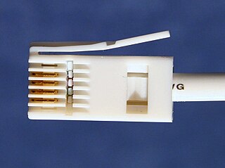
British telephone sockets were introduced in their current plug and socket form on 19 November 1981 by British Telecom to allow subscribers to connect their own telephones. The connectors are specified in British Standard BS 6312. Electrical characteristics of the telephone interface are specified by individual network operators, e.g. in British Telecom's SIN 351. Electrical characteristics required of British telephones used to be specified in BS 6305.
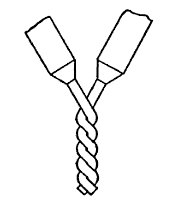
A rat-tail splice, also known as a twist splice or a pig-tail splice, is a basic electrical splice that can be done with both solid and stranded wire. It is made by taking two or more bare wires and wrapping them together symmetrically around the common axis of both wires.
ANSI/TIA-568 is a technical standard for commercial building cabling for telecommunications products and services. The title of the standard is Commercial Building Telecommunications Cabling Standard and is published by the Telecommunications Industry Association (TIA), a body accredited by the American National Standards Institute (ANSI).
Copper has been used in electrical wiring since the invention of the electromagnet and the telegraph in the 1820s. The invention of the telephone in 1876 created further demand for copper wire as an electrical conductor.

A towing sock or wire rope puller or wire pulling grip is a device that connects to the end of a cable, such as a power cable, in order to pull it through a tube or tunnel. It works by tightening around the cable when pulled, in the same manner as a Chinese finger trap. The towing sock is tubular and made of braided cable, open at one end and closed at the other where it connects to a tow line using an eye splice.
