
A Ludwieg tube is a cheap and efficient way of producing supersonic flow. Mach numbers up to 4 in air are easily obtained without any additional heating of the flow. With heating, Mach numbers of up to 11 can be reached.
A Ludwieg tube is a cheap and efficient way of producing supersonic flow. Mach numbers up to 4 in air are easily obtained without any additional heating of the flow. With heating, Mach numbers of up to 11 can be reached.
A Ludwieg tube is a wind tunnel that produces supersonic flow for short periods of time. A large evacuated dump tank is separated from the downstream end of a convergent-divergent nozzle by a diaphragm or fast acting valve. The upstream end of the nozzle connects to a long cylindrical tube, whose cross-sectional area is significantly larger than the throat area of the nozzle. Initially, the pressure in the nozzle and tube is high. To start the tunnel, the diaphragm is ruptured, e.g., by piercing it with a suitable cutting device, or opening the valve respectively. As always when a diaphragm ruptures, a shock wave propagates into the low-pressure region (here the dump tank) and an expansion wave propagates into the high-pressure region (here the nozzle and the long tube). As this unsteady expansion propagates through the long tube, it sets up a steady subsonic flow toward the nozzle, which is accelerated by the convergent-divergent nozzle to a supersonic condition. The flow is steady until the expansion, having been reflected from the far end of the tube, arrives at the nozzle again. For practical reasons, flow times are about 100 milliseconds for most Ludwieg tubes. [1] For many purposes, this flow duration is sufficient. However, by taking advantage of multiple quasi-static flows between expansion wave reflections, experimentation times of up to 6 seconds can be achieved. [2]

Wind tunnels are large tubes with air moving inside. The tunnels are used to copy the actions of an object in flight. Researchers use wind tunnels to learn more about how an aircraft will fly. NASA uses wind tunnels to test scale models of aircraft and spacecraft. Some wind tunnels are big enough to hold full-size versions of vehicles. The wind tunnel moves air around an object, making it seem like the object is really flying.
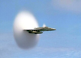
In physics, a shock wave, or shock, is a type of propagating disturbance that moves faster than the local speed of sound in the medium. Like an ordinary wave, a shock wave carries energy and can propagate through a medium but is characterized by an abrupt, nearly discontinuous, change in pressure, temperature, and density of the medium.
The speed of sound is the distance travelled per unit time by a sound wave as it propagates through an elastic medium. At 20 °C (68 °F), the speed of sound in air is about 343 metres per second, or a kilometre in 2.9 s or a mile in 4.7 s. It depends strongly on temperature, but also varies by several metres per second, depending on which gases exist in the medium through which a soundwave is propagating.
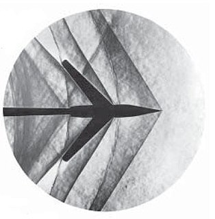
The Ludwieg tube was invented by Hubert Ludwieg (1912-2000) in 1955 in response to a competition for a transonic or supersonic wind tunnel design that would be capable of producing high Reynolds number at low operating cost. Professor Ludwieg was also responsible for the experimental demonstration and explanation of the large effect of sweep on the drag of transonic wings (his dissertation in 1937).
In aeronautics, transonic flight is flying at or near the speed of sound 343 meters per second, relative to the air through which the vehicle is traveling. A typical convention used is to define transonic flight as speeds in the range of Mach 0.72 to 1.0.

The Reynolds number is an important dimensionless quantity in fluid mechanics used to help predict flow patterns in different fluid flow situations. At low Reynolds numbers, flows tend to be dominated by laminar (sheet-like) flow, while at high Reynolds numbers turbulence results from differences in the fluid's speed and direction, which may sometimes intersect or even move counter to the overall direction of the flow. These eddy currents begin to churn the flow, using up energy in the process, which for liquids increases the chances of cavitation. The Reynolds number has wide applications, ranging from liquid flow in a pipe to the passage of air over an aircraft wing. It is used to predict the transition from laminar to turbulent flow, and is used in the scaling of similar but different-sized flow situations, such as between an aircraft model in a wind tunnel and the full size version. The predictions of the onset of turbulence and the ability to calculate scaling effects can be used to help predict fluid behaviour on a larger scale, such as in local or global air or water movement and thereby the associated meteorological and climatological effects.
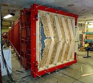
The shock tube is an instrument used to replicate and direct blast waves at a sensor or a model in order to simulate actual explosions and their effects, usually on a smaller scale. Shock tubes can also be used to study aerodynamic flow under a wide range of temperatures and pressures that are difficult to obtain in other types of testing facilities. Shock tubes are also used to investigate compressible flow phenomena and gas phase combustion reactions. More recently, shock tubes have been used in biomedical research to study how biological specimens are affected by blast waves.

A supersonic wind tunnel is a wind tunnel that produces supersonic speeds (1.2<M<5) The Mach number and flow are determined by the nozzle geometry. The Reynolds number is varied by changing the density level. Therefore, a high pressure ratio is required. Apart from that, condensation of moisture or even gas liquefaction can occur if the static temperature becomes cold enough. This means that a supersonic wind tunnel usually needs a drying or a pre-heating facility. A supersonic wind tunnel has a large power demand, so most are designed for intermittent instead of continuous operation.

A hypersonic wind tunnel is designed to generate a hypersonic flow field in the working section, thus simulating the typical flow features of this flow regime - including compression shocks and pronounced boundary layer effects, entropy layer and viscous interaction zones and most importantly high total temperatures of the flow. The speed of these tunnels vary from Mach 5 to 15. The power requirement of a wind tunnel increases with the cross section, the flow density and is directly proportional to the third power of the test velocity. Hence installation of a continuous, closed circuit wind tunnel remains a costly affair. The first continuous Mach 7-10 wind tunnel with 1x1 m test section was planned at Kochel am See, Germany during WW II and finally put into operation as 'Tunnel A' in the late 1950s at AEDC Tullahoma, TN, USA for an installed power of 57 MW. In view of these high facility demands, also intermittently operated experimental facilities like blow-down wind tunnels are designed and installed to simulate the hypersonic flow. A hypersonic wind tunnel comprises in flow direction the main components: heater/cooler arrangements, dryer, convergent/divergent nozzle, test section, second throat and diffuser. A blow-down wind tunnel has a low vacuum reservoir at the back end, while a continuously operated, closed circuit wind tunnel has a high power compressor installation instead. Since the temperature drops with the expanding flow, the air inside the test section has the chance of becoming liquefied. For that reason, preheating is particularly critical.
In fluid dynamics, the Mach number is a dimensionless quantity representing the ratio of flow velocity past a boundary to the local speed of sound.

In aerodynamics, a hypersonic speed is one that greatly exceeds the speed of sound, often stated as starting at speeds of Mach 5 and above.
Compressible flow is the branch of fluid mechanics that deals with flows having significant changes in fluid density. While all flows are compressible, flows are usually treated as being incompressible when the Mach number is less than 0.3. The study of compressible flow is relevant to high-speed aircraft, jet engines, rocket motors, high-speed entry into a planetary atmosphere, gas pipelines, commercial applications such as abrasive blasting, and many other fields.

A nozzle is a device designed to control the direction or characteristics of a fluid flow as it exits an enclosed chamber or pipe.
In fluid dynamics, a Mach wave is a pressure wave traveling with the speed of sound caused by a slight change of pressure added to a compressible flow. These weak waves can combine in supersonic flow to become a shock wave if sufficient Mach waves are present at any location. Such a shock wave is called a Mach stem or Mach front. Thus, it is possible to have shockless compression or expansion in a supersonic flow by having the production of Mach waves sufficiently spaced. A Mach wave is the weak limit of an oblique shock wave.
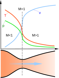
A de Laval nozzle is a tube that is pinched in the middle, making a carefully balanced, asymmetric hourglass shape. It is used to accelerate a hot, pressurized gas passing through it to a higher supersonic speed in the axial (thrust) direction, by converting the heat energy of the flow into kinetic energy. Because of this, the nozzle is widely used in some types of steam turbines and rocket engine nozzles. It also sees use in supersonic jet engines.
A propelling nozzle is a nozzle that converts the internal energy of a working gas into propulsive force; it is the nozzle, which forms a jet, that separates a gas turbine, being gas generator, from a jet engine.
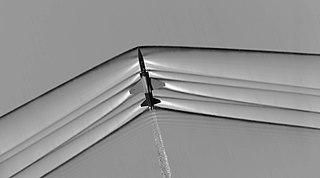
An oblique shock wave, unlike a normal shock, is inclined with respect to the incident upstream flow direction. It will occur when a supersonic flow encounters a corner that effectively turns the flow into itself and compresses. The upstream streamlines are uniformly deflected after the shock wave. The most common way to produce an oblique shock wave is to place a wedge into supersonic, compressible flow. Similar to a normal shock wave, the oblique shock wave consists of a very thin region across which nearly discontinuous changes in the thermodynamic properties of a gas occur. While the upstream and downstream flow directions are unchanged across a normal shock, they are different for flow across an oblique shock wave.
Choked flow is a compressible flow effect. The parameter that becomes "choked" or "limited" is the fluid velocity.

Shock diamonds are a formation of standing wave patterns that appear in the supersonic exhaust plume of an aerospace propulsion system, such as a supersonic jet engine, rocket, ramjet, or scramjet, when it is operated in an atmosphere. The "diamonds" are actually a complex flow field made visible by abrupt changes in local density and pressure as the exhaust passes through a series of standing shock waves and expansion fans. Mach diamonds are named after Ernst Mach, the physicist who first described them.
The University of Texas at Arlington Aerodynamics Research Center (ARC) is a facility located in the southeast portion of the campus operated under the Department of Mechanical and Aerospace Engineering. It was established in 1986 as part of an expansion of UTA's College of Engineering. The ARC contributes to the vision of UTA and the University of Texas System to transform the university into a full-fledged research institution. It showcases the aerodynamics research activities at UTA and, in its history, has established itself as a unique facility at a university level. The wind tunnels and equipment in the facility were mainly built by scouting for and upgrading decommissioned equipment from the government and industry. Currently, Masters and Ph.D. students perform research in the fields of high-speed gas dynamics, propulsion, and Computational fluid dynamics among other projects related to aerodynamics.
Expansion and shock tunnels are aerodynamic testing facilities with a specific interest in high speeds and high temperature testing. Shock tunnels use steady flow nozzle expansion whereas expansion tunnels use unsteady expansion with higher enthalpy, or thermal energy. In both cases the gases are compressed and heated until the gases are released, expanding rapidly down the expansion chamber. The tunnels reach speeds from Mach 3 to Mach 30 to create testing conditions that simulate hypersonic to re-entry flight. These tunnels are used by military and government agencies to test hypersonic vehicles that undergo a variety of natural phenomenon that occur during hypersonic flight.
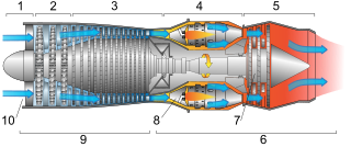
This article briefly describes the components and systems found in jet engines.

AEDC Hypervelocity Wind Tunnel 9 is a hypersonic wind tunnel owned by the United States Air Force and operated by National Aerospace Solutions The facility can generate high Mach numbers and high Reynolds for hypersonic ground testing and the validation of computational simulations for the Air Force and Department of Defense.

The MARHy Hypersonic low density Wind Tunnel, located at the ICARE Laboratory in Orléans, France, is a research facility used extensively for fundamental and applied research of fluid dynamic phenomena in rarefied compressible flows. Its name is an acronym for Mach Adaptable Rarefied Hypersonic and the wind tunnel is recorded under this name under the European portal MERIL.