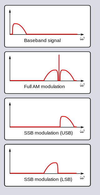
In radio communications, single-sideband modulation (SSB) or single-sideband suppressed-carrier modulation (SSB-SC) is a type of modulation used to transmit information, such as an audio signal, by radio waves. A refinement of amplitude modulation, it uses transmitter power and bandwidth more efficiently. Amplitude modulation produces an output signal the bandwidth of which is twice the maximum frequency of the original baseband signal. Single-sideband modulation avoids this bandwidth increase, and the power wasted on a carrier, at the cost of increased device complexity and more difficult tuning at the receiver.
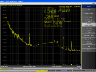
In signal processing, phase noise is the frequency-domain representation of random fluctuations in the phase of a waveform, corresponding to time-domain deviations from perfect periodicity (jitter). Generally speaking, radio-frequency engineers speak of the phase noise of an oscillator, whereas digital-system engineers work with the jitter of a clock.
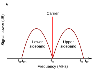
In radio communications, a sideband is a band of frequencies higher than or lower than the carrier frequency, that are the result of the modulation process. The sidebands carry the information transmitted by the radio signal. The sidebands comprise all the spectral components of the modulated signal except the carrier. The signal components above the carrier frequency constitute the upper sideband (USB), and those below the carrier frequency constitute the lower sideband (LSB). All forms of modulation produce sidebands.

In telecommunication, especially radio communication, spread spectrum are techniques by which a signal generated with a particular bandwidth is deliberately spread in the frequency domain over a wider frequency band. Spread-spectrum techniques are used for the establishment of secure communications, increasing resistance to natural interference, noise, and jamming, to prevent detection, to limit power flux density, and to enable multiple-access communications.
A signal generator is one of a class of electronic devices that generates electrical signals with set properties of amplitude, frequency, and wave shape. These generated signals are used as a stimulus for electronic measurements, typically used in designing, testing, troubleshooting, and repairing electronic or electroacoustic devices, though it often has artistic uses as well.

A spectrum analyzer measures the magnitude of an input signal versus frequency within the full frequency range of the instrument. The primary use is to measure the power of the spectrum of known and unknown signals. The input signal that most common spectrum analyzers measure is electrical; however, spectral compositions of other signals, such as acoustic pressure waves and optical light waves, can be considered through the use of an appropriate transducer. Spectrum analyzers for other types of signals also exist, such as optical spectrum analyzers which use direct optical techniques such as a monochromator to make measurements.

Intermodulation (IM) or intermodulation distortion (IMD) is the amplitude modulation of signals containing two or more different frequencies, caused by nonlinearities or time variance in a system. The intermodulation between frequency components will form additional components at frequencies that are not just at harmonic frequencies of either, like harmonic distortion, but also at the sum and difference frequencies of the original frequencies and at sums and differences of multiples of those frequencies.

A vector signal analyzer is an instrument that measures the magnitude and phase of the input signal at a single frequency within the IF bandwidth of the instrument. The primary use is to make in-channel measurements, such as error vector magnitude, code domain power, and spectral flatness, on known signals.

An antenna analyzer or in British aerial analyser is a device used for measuring the input impedance of antenna systems in radio electronics applications.

Electromagnetic interference (EMI), also called radio-frequency interference (RFI) when in the radio frequency spectrum, is a disturbance generated by an external source that affects an electrical circuit by electromagnetic induction, electrostatic coupling, or conduction. The disturbance may degrade the performance of the circuit or even stop it from functioning. In the case of a data path, these effects can range from an increase in error rate to a total loss of the data. Both human-made and natural sources generate changing electrical currents and voltages that can cause EMI: ignition systems, cellular network of mobile phones, lightning, solar flares, and auroras. EMI frequently affects AM radios. It can also affect mobile phones, FM radios, and televisions, as well as observations for radio astronomy and atmospheric science.

Continuous-wave radar is a type of radar system where a known stable frequency continuous wave radio energy is transmitted and then received from any reflecting objects. Individual objects can be detected using the Doppler effect, which causes the received signal to have a different frequency from the transmitted signal, allowing it to be detected by filtering out the transmitted frequency.

A lock-in amplifier is a type of amplifier that can extract a signal with a known carrier wave from an extremely noisy environment. Depending on the dynamic reserve of the instrument, signals up to a million times smaller than noise components, potentially fairly close by in frequency, can still be reliably detected. It is essentially a homodyne detector followed by low-pass filter that is often adjustable in cut-off frequency and filter order.

A network analyzer is an instrument that measures the network parameters of electrical networks. Today, network analyzers commonly measure s–parameters because reflection and transmission of electrical networks are easy to measure at high frequencies, but there are other network parameter sets such as y-parameters, z-parameters, and h-parameters. Network analyzers are often used to characterize two-port networks such as amplifiers and filters, but they can be used on networks with an arbitrary number of ports.

Explorer 52, also known as Hawkeye-1, Injun-F, Neutral Point Explorer, IE-D, Ionospheric Explorer-D, was a NASA satellite launched on 3 June 1974, from Vandenberg Air Force Base on a Scout E-1 launch vehicle.
A quasi-peak detector is a type of electronic detector or rectifier. Quasi-peak detectors for specific purposes have usually been standardized with mathematically precisely defined dynamic characteristics of attack time, integration time, and decay time or fall-back time.
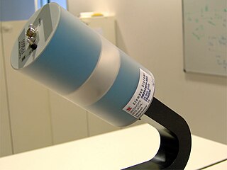
EMF measurements are measurements of ambient (surrounding) electromagnetic fields that are performed using particular sensors or probes, such as EMF meters. These probes can be generally considered as antennas although with different characteristics. In fact, probes should not perturb the electromagnetic field and must prevent coupling and reflection as much as possible in order to obtain precise results. There are two main types of EMF measurements:

A signal analyzer is an instrument that measures the magnitude and phase of the input signal at a single frequency within the IF bandwidth of the instrument. It employs digital techniques to extract useful information that is carried by an electrical signal. In common usage the term is related to both spectrum analyzers and vector signal analyzers. While spectrum analyzers measure the amplitude or magnitude of signals, a signal analyzer with appropriate software or programming can measure any aspect of the signal such as modulation. Today’s high-frequency signal analyzers achieve good performance by optimizing both the analog front end and the digital back end.

The ISEE-1 was an Explorer-class mother spacecraft, International Sun-Earth Explorer-1, was part of the mother/daughter/heliocentric mission. ISEE-1 was a 340.2 kg (750 lb) space probe used to study magnetic fields near the Earth. ISEE-1 was a spin-stabilized spacecraft and based on the design of the prior IMP series of spacecraft. ISEE-1 and ISEE-2 were launched on 22 October 1977, and they re-entered on 26 September 1987.

Explorer 45 was a NASA satellite launched as part of Explorer program. Explorer 45 was the only one to be released from the program Small Scientific Satellite.