
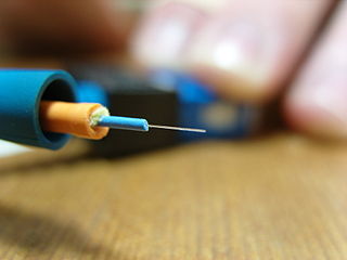
In fiber-optic communication, a single-mode optical fiber (SMF), also known as fundamental- or mono-mode, is an optical fiber designed to carry only a single mode of light - the transverse mode. Modes are the possible solutions of the Helmholtz equation for waves, which is obtained by combining Maxwell's equations and the boundary conditions. These modes define the way the wave travels through space, i.e. how the wave is distributed in space. Waves can have the same mode but have different frequencies. This is the case in single-mode fibers, where we can have waves with different frequencies, but of the same mode, which means that they are distributed in space in the same way, and that gives us a single ray of light. Although the ray travels parallel to the length of the fiber, it is often called transverse mode since its electromagnetic oscillations occur perpendicular (transverse) to the length of the fiber. The 2009 Nobel Prize in Physics was awarded to Charles K. Kao for his theoretical work on the single-mode optical fiber. The standards G.652 and G.657 define the most widely used forms of single-mode optical fiber.

HIPPI, short for High Performance Parallel Interface, is a computer bus for the attachment of high speed storage devices to supercomputers, in a point-to-point link. It was popular in the late 1980s and into the mid-to-late 1990s, but has since been replaced by ever-faster standard interfaces like Fibre Channel and 10 Gigabit Ethernet.

A dark fibre or unlit fibre is an unused optical fibre, available for use in fibre-optic communication. Dark fibre may be leased from a network service provider.
Multi-mode optical fiber is a type of optical fiber mostly used for communication over short distances, such as within a building or on a campus. Multi-mode links can be used for data rates up to 800 Gbit/s. Multi-mode fiber has a fairly large core diameter that enables multiple light modes to be propagated and limits the maximum length of a transmission link because of modal dispersion. The standard G.651.1 defines the most widely used forms of multi-mode optical fiber.

An optical fiber, or optical fibre, is a flexible glass or plastic fiber that can transmit light from one end to the other. Such fibers find wide usage in fiber-optic communications, where they permit transmission over longer distances and at higher bandwidths than electrical cables. Fibers are used instead of metal wires because signals travel along them with less loss and are immune to electromagnetic interference. Fibers are also used for illumination and imaging, and are often wrapped in bundles so they may be used to carry light into, or images out of confined spaces, as in the case of a fiberscope. Specially designed fibers are also used for a variety of other applications, such as fiber optic sensors and fiber lasers.

Fiber to the x or fiber in the loop is a generic term for any broadband network architecture using optical fiber to provide all or part of the local loop used for last mile telecommunications. As fiber optic cables are able to carry much more data than copper cables, especially over long distances, copper telephone networks built in the 20th century are being replaced by fiber.
Cable jetting is a technique to install cables in ducts. It is commonly used to install cables with optical fibers in underground polyethylene ducts and is an alternative to pulling.
A photonic integrated circuit (PIC) or integrated optical circuit is a microchip containing two or more photonic components that form a functioning circuit. This technology detects, generates, transports, and processes light. Photonic integrated circuits utilize photons as opposed to electrons that are utilized by electronic integrated circuits. The major difference between the two is that a photonic integrated circuit provides functions for information signals imposed on optical wavelengths typically in the visible spectrum or near infrared (850–1650 nm).

Fiber-optic communication is a method of transmitting information from one place to another by sending pulses of infrared or visible light through an optical fiber. The light is a form of carrier wave that is modulated to carry information. Fiber is preferred over electrical cabling when high bandwidth, long distance, or immunity to electromagnetic interference is required. This type of communication can transmit voice, video, and telemetry through local area networks or across long distances.

Telecommunications engineering is a subfield of electronics engineering which seeks to design and devise systems of communication at a distance. The work ranges from basic circuit design to strategic mass developments. A telecommunication engineer is responsible for designing and overseeing the installation of telecommunications equipment and facilities, such as complex electronic switching system, and other plain old telephone service facilities, optical fiber cabling, IP networks, and microwave transmission systems. Telecommunications engineering also overlaps with broadcast engineering.

A fiber-optic cable, also known as an optical-fiber cable, is an assembly similar to an electrical cable but containing one or more optical fibers that are used to carry light. The optical fiber elements are typically individually coated with plastic layers and contained in a protective tube suitable for the environment where the cable is used. Different types of cable are used for fiber-optic communication in different applications, for example long-distance telecommunication or providing a high-speed data connection between different parts of a building.

Fiber to the Edge (FTTE), fiber to the telecom enclosure (FTTTE), fiber to the zone (FTTZ), or fibre to the cabinet (FTTC) in the UK, is a networking approach used in the enterprise building. It is a standards-compliant structured cabling system architecture that extends the optical fiber backbone network from the equipment room directly to a telecommunications enclosure (TE), access node, ONT, or media converter installed in a common space to serve a number of users or devices in a nearby area.
Fiber Optic cable termination is the addition of connectors to each optical fiber in a cable. The fibers need to have connectors fitted before they can attach to other equipment. Two common solutions for fiber cable termination are pigtails and fanout kits or breakout kits.
A fiber management system (FMS) manages optical fiber connections from outside of fiber rack to the fiber routers. Fiber-optic cable duct containing many fibers comes from far end sites and terminates on the FMS using splicing technology. FMS has fiber in and fiber out ports. From fiber out port the fiber patch will go to fiber optics based router.

Hybrid solar lighting (HSL) or hybrid lighting systems combine the use of solar with artificial light for interior illumination by channelling sunlight through fiber optic cable bundles to provide solar light into rooms without windows or skylights, and by supplementing this natural light with artificial light—typically LED—as required.
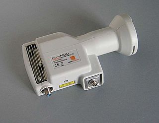
Fibre satellite distribution is a technology that enables satellite TV signals from an antenna to be distributed using an optical fibre cable infrastructure and then converted to electrical signals for use with conventional set-top box receivers.

Optical attached cable (OPAC) is a type of fibre-optic cable that is installed by being attached to a host conductor along overhead power lines. The attachment system varies and can include wrapping, lashing or clipping the fibre-optic cable to the host. Installation is typically performed using a specialised piece of equipment that travels along the host conductor from pole to pole or tower to tower, wrapping, clipping or lashing the fibre-optic cable in place. Different manufacturers have different systems and the installation equipment, cable designs and hardware are not interchangeable.
A cable blowing machine is a machine designed to fit fiber optic cables into telecommunication ducts and microducts with the use of compressed air or water.

Fiber to the office (FTTO) is an alternative cabling concept for local area network (LAN) network office environments. It combines passive elements and active mini-switches to provide end devices with Gigabit Ethernet. FTTO involves centralised optical fibre cabling techniques to create a combined backbone/horizontal channel; this channel is provided from the work areas to the centralised cross-connect or interconnect by allowing the use of pull-through cables or splices in the telecommunications room.


