
Amplitude modulation (AM) is a modulation technique used in electronic communication, most commonly for transmitting messages with a radio wave. In amplitude modulation, the amplitude of the wave is varied in proportion to that of the message signal, such as an audio signal. This technique contrasts with angle modulation, in which either the frequency of the carrier wave is varied, as in frequency modulation, or its phase, as in phase modulation.

Analog television is the original television technology that uses analog signals to transmit video and audio. In an analog television broadcast, the brightness, colors and sound are represented by amplitude, phase and frequency of an analog signal.
In electronics and telecommunications, modulation is the process of varying one or more properties of a periodic waveform, called the carrier signal, with a separate signal called the modulation signal that typically contains information to be transmitted. For example, the modulation signal might be an audio signal representing sound from a microphone, a video signal representing moving images from a video camera, or a digital signal representing a sequence of binary digits, a bitstream from a computer.

A superheterodyne receiver, often shortened to superhet, is a type of radio receiver that uses frequency mixing to convert a received signal to a fixed intermediate frequency (IF) which can be more conveniently processed than the original carrier frequency. It was invented by French radio engineer and radio manufacturer Lucien Lévy. Virtually all modern radio receivers use the superheterodyne principle.

Delta modulation is an analog-to-digital and digital-to-analog signal conversion technique used for transmission of voice information where quality is not of primary importance. DM is the simplest form of differential pulse-code modulation (DPCM) where the difference between successive samples is encoded into n-bit data streams. In delta modulation, the transmitted data are reduced to a 1-bit data stream representing either up (↗) or down (↘). Its main features are:

In signal processing, pre-emphasis is a technique to protect against anticipated noise and loss. The idea is to boost the frequency range that is most susceptible to noise and loss beforehand, so that after a noisy and lossy process more information can be recovered from that frequency range. Removal of the distortion caused by pre-emphasis is called de-emphasis, making the output accurately reproduce the original input.
In telecommunication, intersymbol interference (ISI) is a form of distortion of a signal in which one symbol interferes with subsequent symbols. This is an unwanted phenomenon as the previous symbols have a similar effect as noise, thus making the communication less reliable. The spreading of the pulse beyond its allotted time interval causes it to interfere with neighboring pulses. ISI is usually caused by multipath propagation or the inherent linear or non-linear frequency response of a communication channel causing successive symbols to blur together.
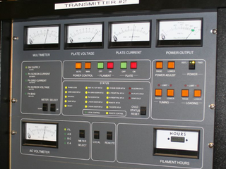
In electronics and telecommunications, a radio transmitter or just transmitter is an electronic device which produces radio waves with an antenna with the purpose of signal transmission up to a radio receiver. The transmitter itself generates a radio frequency alternating current, which is applied to the antenna. When excited by this alternating current, the antenna radiates radio waves.
Demodulation is extracting the original information-bearing signal from a carrier wave. A demodulator is an electronic circuit that is used to recover the information content from the modulated carrier wave. There are many types of modulation so there are many types of demodulators. The signal output from a demodulator may represent sound, images or binary data.

Automatic gain control (AGC) is a closed-loop feedback regulating circuit in an amplifier or chain of amplifiers, the purpose of which is to maintain a suitable signal amplitude at its output, despite variation of the signal amplitude at the input. The average or peak output signal level is used to dynamically adjust the gain of the amplifiers, enabling the circuit to work satisfactorily with a greater range of input signal levels. It is used in most radio receivers to equalize the average volume (loudness) of different radio stations due to differences in received signal strength, as well as variations in a single station's radio signal due to fading. Without AGC the sound emitted from an AM radio receiver would vary to an extreme extent from a weak to a strong signal; the AGC effectively reduces the volume if the signal is strong and raises it when it is weaker. In a typical receiver the AGC feedback control signal is usually taken from the detector stage and applied to control the gain of the IF or RF amplifier stages.
A continuous wave or continuous waveform (CW) is an electromagnetic wave of constant amplitude and frequency, typically a sine wave, that for mathematical analysis is considered to be of infinite duration. It may refer to e.g. a laser or particle accelerator having a continuous output, as opposed to a pulsed output.
This is an index of articles relating to electronics and electricity or natural electricity and things that run on electricity and things that use or conduct electricity.

In radio communications, a radio receiver, also known as a receiver, a wireless, or simply a radio, is an electronic device that receives radio waves and converts the information carried by them to a usable form. It is used with an antenna. The antenna intercepts radio waves and converts them to tiny alternating currents which are applied to the receiver, and the receiver extracts the desired information. The receiver uses electronic filters to separate the desired radio frequency signal from all the other signals picked up by the antenna, an electronic amplifier to increase the power of the signal for further processing, and finally recovers the desired information through demodulation.
Video modulation is a strategy of transmitting video signal in the field of radio modulation and television technology. This strategy enables the video signal to be transmitted more efficiently through long distances. In general, video modulation means that a higher frequency carrier wave is modified according to the original video signal. In this way, carrier wave contains the information in the video signal. Then, the carrier will "carry" the information in the form of radio frequency (RF) signal. When carrier reaches its destination, the video signal is extracted from the carrier by decoding. In other words, the video signal is first combined with a higher frequency carrier wave so that carrier wave contains the information in video signal. The combined signal is called radio-frequency signal. At the end of this transmitting system, the RF signals stream from a light sensor and hence, the receivers can obtain the initial data in the original video signal.

Continuous-wave radar is a type of radar system where a known stable frequency continuous wave radio energy is transmitted and then received from any reflecting objects. Individual objects can be detected using the Doppler effect, which causes the received signal to have a different frequency from the transmitted signal, allowing it to be detected by filtering out the transmitted frequency.

Delta-sigma modulation is an oversampling method for encoding signals into low bit depth digital signals at a very high sample-frequency as part of the process of delta-sigma analog-to-digital converters (ADCs) and digital-to-analog converters (DACs). Delta-sigma modulation achieves high quality by utilizing a negative feedback loop during quantization to the lower bit depth that continuously corrects quantization errors and moves quantization noise to higher frequencies well above the original signal's bandwidth. Subsequent low-pass filtering for demodulation easily removes this high frequency noise and time averages to achieve high accuracy in amplitude which can be ultimately encoded as pulse-code modulation (PCM).
A radio transmitter or just transmitter is an electronic device which produces radio waves with an antenna. Radio waves are electromagnetic waves with frequencies between about 30 Hz and 300 GHz. The transmitter itself generates a radio frequency alternating current, which is applied to the antenna. When excited by this alternating current, the antenna radiates radio waves. Transmitters are necessary parts of all systems that use radio: radio and television broadcasting, cell phones, wireless networks, radar, two way radios like walkie talkies, radio navigation systems like GPS, remote entry systems, among numerous other uses.
Radio receiver design includes the electronic design of different components of a radio receiver which processes the radio frequency signal from an antenna in order to produce usable information such as audio. The complexity of a modern receiver and the possible range of circuitry and methods employed are more generally covered in electronics and communications engineering. The term radio receiver is understood in this article to mean any device which is intended to receive a radio signal in order to generate useful information from the signal, most notably a recreation of the so-called baseband signal which modulated the radio signal at the time of transmission in a communications or broadcast system.

In radio, a detector is a device or circuit that extracts information from a modulated radio frequency current or voltage. The term dates from the first three decades of radio (1888–1918). Unlike modern radio stations which transmit sound on an uninterrupted carrier wave, early radio stations transmitted information by radiotelegraphy. The transmitter was switched on and off to produce long or short periods of radio waves, spelling out text messages in Morse code. Therefore, early radio receivers could reproduce the Morse code "dots" and "dashes" by simply distinguishing between the presence or absence of a radio signal. The device that performed this function in the receiver circuit was called a detector. A variety of different detector devices, such as the coherer, electrolytic detector, magnetic detector and the crystal detector, were used during the wireless telegraphy era until superseded by vacuum tube technology.
A frequency synthesizer is an electronic circuit that generates a range of frequencies from a single reference frequency. Frequency synthesizers are used in many modern devices such as radio receivers, televisions, mobile telephones, radiotelephones, walkie-talkies, CB radios, cable television converter boxes, satellite receivers, and GPS systems. A frequency synthesizer may use the techniques of frequency multiplication, frequency division, direct digital synthesis, frequency mixing, and phase-locked loops to generate its frequencies. The stability and accuracy of the frequency synthesizer's output are related to the stability and accuracy of its reference frequency input. Consequently, synthesizers use stable and accurate reference frequencies, such as those provided by a crystal oscillator.
