Open channel spillway

Last updated
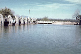
Spillway channel example at the Colt Crag Reservoir Spillway channel Colt Crag Reservoir - geograph.org.uk - 1008550.jpg
Spillway channel example at the Colt Crag Reservoir

Open channel spillways are dam spillways that utilize the principles of open-channel flow to convey impounded water in order to prevent dam failure. They can function as principal spillways, emergency spillways, or both. They can be located on the dam itself or on a natural grade in the vicinity of the dam.

Contents

Spillway types

Chute spillway Chute Spillway.jpg
Chute spillway

Chute spillway

Chute spillways carry supercritical flow through the steep slope of an open channel. There are four main components of a chute spillway: [1] The elements of a spillway are the inlet, the vertical curve section (ogee curve), the steep-sloped channel and the outlet.

In order to avoid a hydraulic jump, the slope of the spillway must be steep enough for the flow to remain supercritical.

Proper spillways help with flood control, prevent erosion at the ends of terraces, outlets, and waterways, reduce runoff over drainage ditch banks and are simple to construct.

However, they can only be constructed at sites with natural drainage and moderate temperature variation and have a shorter life expectancy than other spillways.

Stepped spillways

Stepped spillways are used to dissipate energy along the chute of the channel. The steps of the spillway greatly reduce the kinetic energy of the flow and therefore reduce flow velocity. Roller-compacted concrete (RCC) stepped spillways have become increasingly popular because of their use in rehabilitating aged flood control dams. [2]

Stepped spillway Stepped Spillway.jpg
Stepped spillway

Design guidelines for these spillways are limited. However, research attempts to assist engineers. The two main design components are the inception point (where flow bulking first occurs—increased flow depth) and the energy dissipation that occurs. [2]

Stepped spillways are useful for flood control, increasing dissolved oxygen (DO) levels downstream of a dam, aid wastewater treatment plants for air-water transfer of gases and for volatile organic compound (VOC) removal and reduces the spillway length or eliminates need for stilling basin. [3]

However, few design guidelines are in place and stepped spillways have only been successful for small unit discharges where step height can influence the flow. [3]

Side channel spillways

Side channel spillways are typically used to discharge floods perpendicular to the general direction of flow by placing the control weir parallel to the upper portion of the discharge channel. [4]

It offers low flow velocities upstream and minimizes erosion.

However, it can cause a sudden increase in reservoir level if the channel is submerged.

Flow rates

Different agencies have different methods and formulas for quantifying flows and conveyance capacities for chute spillways. The Natural Resources Conservation Service (NRCS) produced handbooks on dam design. In the National Engineering Handbook, Section 14, Chute Spillways (NEH14), [5] flow equations are given for straight inlets and box inlets.

NEH14 provides the following discharge-head relationship for straight inlets of chute spillways, which is given by the flow equation for a weir:

Q = 3.1W[H + va2/2g]3/2 = 3.1He3/2

where:

Straight inlet

Straight inlet Straight Inlet.jpg
Straight inlet

If the flow rate per unit width is defined as q = Q/W, then the equation can be written as: [5]

q = Q/W = 3.1[H + va2/2g]3/2 = 3.1He3/2

The coefficient, 3.1 varies for different entrance conditions. The value of the coefficient is slightly higher if the conveyance channel has a greater width than the inlet. The value 3.1 is based on the assumption that He and va are measured at a location that exhibits subcritical flow conditions.

NEH14 also provides the following relationship for side channel inlets:

Qmi = 3.1Lh3/2

where:

Side channel inlet

Side channel inlet Side Channel Inlet.jpg
Side channel inlet

The United States Bureau of Reclamation (USBR) also uses the weir formula to quantify flow over a chute spillway. The USBR flow equation is: [5] [6]

Q = CLH3/2

where:

For H = 1 ftC = 3.2
23.4
33.6
43.7
53.8

Example: For a spillway crest length/width of 25 ft, Q will vary with H as follows:

Discharge as a function of water surface elevation for NRCS and USBR formulas Discharge as a function of water surface elevation for NRCS and USBR formulas.jpg
Discharge as a function of water surface elevation for NRCS and USBR formulas

For the NRCS computations, the mean velocity of approach was assumed to be zero. For the USBR computations, it was assumed that linear interpolation could be used to obtain C from H. For a given depth at the spillway crest, the flows calculated using the USBR method are higher than those from the NRCS method because of the higher discharge coefficients. C increases with H under the USBR method, whereas C is assumed to be constant with respect to H under the NRCS method.

Flow regimes

Chute spillways

The flow coming into the spillway is subcritical. The slope of the chute causes the flow velocity to increase. Typically, supercritical flow is maintained in the chute.

Stepped spillway

The flow over a stepped spillway is classified as either nappe flow or skimming flow. Nappe flow regimes occur for small discharges and flat slopes. If the discharge is increased or the slope of the channel is increased, a skimming flow regime can occur (Shahheydari et al. 2015). Nappe flow has pockets of air at each step whereas skimming flow does not. The onset of skimming flow can be defined as:

(dc)=1.057*h - 0.465*h2/l

Where:

Image of nappe and skimming flow Skimming and Nappe flow figure.jpg
Image of nappe and skimming flow

Nappe flow

For the nappe flow regime, a partially or fully developed hydraulic jump occurs as a result of the jets created between each step. [7] [8]

Ungated spillway:

Gated spillway:

Where:

  • Hdam = dam crest head above the downstream toe (m)
  • H0 = free surface elevation above the spillway crest (m)
  • Hmax = total head (m)
  • dc = critical flow depth
  • H = head loss (m)

Skimming flow regime

Under a skimming flow regime, water flows in a coherent stream down the step. Water skims the top of each step as it flows down the chute. Recirculating vortices are developed between each step which allow the water to flow over the top of the vortices and skim over each step. [7]

=====Energy dissipation===== [7]

Un-gated spillway:

Gated spillway:

where:

  • Hdam = dam crest head above the downstream toe (m)
  • H0 = free surface elevation above the spillway crest (m)
  • Hmax = maximum head available (m)
  • dc = critical flow depth (m)
  • H = head loss (m)
  • f = friction factor
  • α = channel slope [rad]

Cavitation

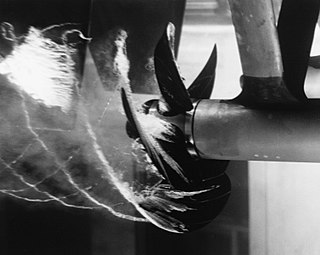
Cavitation is the formation of a void, such as a bubble, within a liquid. A fluid passes from a liquid state to a vapor state due to a change in the local pressure while the temperature remains constant. In the case of a dam spillway, this can be caused by turbulence or vortices in flowing water.

Cavitation occurs within the body of flow of a given distributed roughness. However, the exact location where it will occur cannot be predicted. In the case of chute spillways, cavitation occurs at velocities between 12 and 15 m/s. [9]

When cavitation occurs on a spillway, it can cause severe damage. This is especially true when the velocities exceed 25 m/s. Therefore, protection is needed at these velocities. Cavitation can be prevented by decreasing the flow velocity or by increasing the boundary pressure. [10]

Energy dissipation

Every dam needs some form of energy dissipation in its discharge structure to prevent erosion and scour on the downstream side of the dam, since these phenomena can result in dam failure. Plunge pools (also called stilling basins) and impact boxes are two examples of energy dissipators used on dams.

Many USBR dams use energy dissipating blocks for chute spillways (also called baffled aprons). These blocks help induce a hydraulic jump to establish subcritical flow conditions on the downstream side of the dam. [11]

The steps on stepped spillways can be used for energy dissipation. However, they tend to be effective only at dissipating energy at low flows (i.e. skimming flow). [7]

See also

Related Research Articles

<span class="mw-page-title-main">Cavitation</span> Low-pressure voids formed in liquids

Cavitation is a phenomenon in which the static pressure of a liquid reduces to below the liquid's vapour pressure, leading to the formation of small vapor-filled cavities in the liquid. When subjected to higher pressure, these cavities, called "bubbles" or "voids", collapse and can generate shock waves that may damage machinery. These shock waves are strong when they are very close to the imploded bubble, but rapidly weaken as they propagate away from the implosion. Cavitation is a significant cause of wear in some engineering contexts. Collapsing voids that implode near to a metal surface cause cyclic stress through repeated implosion. This results in surface fatigue of the metal, causing a type of wear also called "cavitation". The most common examples of this kind of wear are to pump impellers, and bends where a sudden change in the direction of liquid occurs. Cavitation is usually divided into two classes of behavior: inertial cavitation and non-inertial cavitation.
<span class="mw-page-title-main">Hydraulic jump</span> Discharge of high velocity liquid into lower velocity area

A hydraulic jump is a phenomenon in the science of hydraulics which is frequently observed in open channel flow such as rivers and spillways. When liquid at high velocity discharges into a zone of lower velocity, a rather abrupt rise occurs in the liquid surface. The rapidly flowing liquid is abruptly slowed and increases in height, converting some of the flow's initial kinetic energy into an increase in potential energy, with some energy irreversibly lost through turbulence to heat. In an open channel flow, this manifests as the fast flow rapidly slowing and piling up on top of itself similar to how a shockwave forms.

<span class="mw-page-title-main">Weir</span> Artificial river barrier

A weir or low head dam is a barrier across the width of a river that alters the flow characteristics of water and usually results in a change in the height of the river level. Weirs are also used to control the flow of water for outlets of lakes, ponds, and reservoirs. There are many weir designs, but commonly water flows freely over the top of the weir crest before cascading down to a lower level.
<span class="mw-page-title-main">Spillway</span> Structure for controlled release of flows from a dam or levee

A spillway is a structure used to provide the controlled release of water downstream from a dam or levee, typically into the riverbed of the dammed river itself. In the United Kingdom, they may be known as overflow channels. Spillways ensure that water does not damage parts of the structure not designed to convey water.

<span class="mw-page-title-main">Large eddy simulation</span>

Large eddy simulation (LES) is a mathematical model for turbulence used in computational fluid dynamics. It was initially proposed in 1963 by Joseph Smagorinsky to simulate atmospheric air currents, and first explored by Deardorff (1970). LES is currently applied in a wide variety of engineering applications, including combustion, acoustics, and simulations of the atmospheric boundary layer.

<span class="mw-page-title-main">Davis Dam</span> Dam in Arizona, USA

Davis Dam is a dam on the Colorado River about 70 miles (110 km) downstream from Hoover Dam. It stretches across the border between Arizona and Nevada. Originally called Bullhead Dam, Davis Dam was renamed after Arthur Powell Davis, who was the director of the U.S. Bureau of Reclamation from 1914 to 1923. The United States Bureau of Reclamation owns and operates the dam, which was completed in 1951.

<span class="mw-page-title-main">Hydraulic head</span> Specific measurement of liquid pressure above a vertical datum

Hydraulic head or piezometric head is a specific measurement of liquid pressure above a vertical datum.

<span class="mw-page-title-main">Floodgate</span> Adjustable gate used to control water flow

Floodgates, also called stop gates, are adjustable gates used to control water flow in flood barriers, reservoir, river, stream, or levee systems. They may be designed to set spillway crest heights in dams, to adjust flow rates in sluices and canals, or they may be designed to stop water flow entirely as part of a levee or storm surge system. Since most of these devices operate by controlling the water surface elevation being stored or routed, they are also known as crest gates. In the case of flood bypass systems, floodgates sometimes are also used to lower the water levels in a main river or canal channels by allowing more water to flow into a flood bypass or detention basin when the main river or canal is approaching a flood stage.

In a hydraulic circuit, net positive suction head (NPSH) may refer to one of two quantities in the analysis of cavitation:

  1. The Available NPSH (NPSHA): a measure of how close the fluid at a given point is to flashing, and so to cavitation. Technically it is the absolute pressure head minus the vapour pressure of the liquid.
  2. The Required NPSH (NPSHR): the head value at the suction side required to keep the fluid away from cavitating.
<span class="mw-page-title-main">Copeton Dam</span> Dam in New South Wales, Australia

Copeton Dam is a major clay core and rock fill embankment dam with nine radial gates and a gated concrete chute spillway across the Gwydir River upstream of Bingara in the New England region of New South Wales, Australia. The dam's purpose includes environmental flows, hydro-electric power generation, irrigation, and water supply. The impounded reservoir is called Lake Copeton.

In hydraulic engineering, a nappe is a sheet or curtain of water that flows over a weir or dam. The upper and lower water surface have well-defined characteristics that are created by the crest of a dam or weir. Both structures have different features that characterize how a nappe might flow through or over impervious concrete structures. Hydraulic engineers distinguish these two water structures in characterizing and calculating the formation of a nappe. Engineers account for the bathymetry of standing bodies or moving bodies of water. An appropriate crest is built for the dam or weir so that dam failure is not caused by nappe vibration or air cavitation from free-overall structures.

<span class="mw-page-title-main">Drop structure</span>

A drop structure, also known as a grade control, sill, or weir, is a manmade structure, typically small and built on minor streams, or as part of a dam's spillway, to pass water to a lower elevation while controlling the energy and velocity of the water as it passes over. Unlike most dams, drop structures are usually not built for water impoundment, diversion or raising the water level. Mostly built on watercourses with steep gradients, they serve other purposes such as water oxygenation and erosion prevention.

<span class="mw-page-title-main">Tsankov Kamak Hydro Power Plant</span> Dam in Tsankov Kamak downstream of Devin

The Tsankov Kamak Hydroelectric Power Plant, also Tsankov Kamak HPP, comprises an arch dam and hydroelectric power plant (HPP) in Tsankov Kamak, southwestern Bulgaria. It is situated on the Vacha River in Smolyan Province, on the borders of Pazardzhik Province and Plovdiv Province, roughly 40 kilometres (25 mi) southwest of Plovdiv and downstream (north) of the town of Devin. It is a part of the Dospat-Vacha cascade development of the Vacha River involving five dams and power stations within the Devin municipality, 250 kilometres (160 mi) southeast of Sofia. The other four dams are Dospat Dam, Teshel Dam, the Vacha Dam and the Krichim Dam.

<span class="mw-page-title-main">Darbandikhan Dam</span> Dam in Darbandikhan, Kurdistan Region.

The Darbandikhan Dam is a multi-purpose embankment dam on the Diyala River in northern Sulaymaniyah Governorate, Iraq. It was constructed between 1956 and 1961. The purpose of the dam is irrigation, flood control, hydroelectric power production and recreation. Due to poor construction and neglect, the dam and its 249 MW power station have undergone several repairs over the years. A rehabilitation of the power station began in 2007 and was completed in 2013.

<span class="mw-page-title-main">Hubert Chanson</span> Australian engineering academic (born 1961)

Hubert Chanson is a professional engineer and academic in hydraulic engineering and environmental fluid mechanics. Since 1990 he has worked at the University of Queensland.

<span class="mw-page-title-main">Stepped spillway</span> Structure for energy dissipated release of flows from a dam or levee

A stepped spillway is a spillway with steps on the spillway chute to assist in the dissipation of the kinetic energy of the descending water. This eliminates or reduces the need for an additional energy dissipator, such as a body of water, at the end of the spillway downstream.

Hydraulic jump in a rectangular channel, also known as classical jump, is a natural phenomenon that occurs whenever flow changes from supercritical to subcritical flow. In this transition, the water surface rises abruptly, surface rollers are formed, intense mixing occurs, air is entrained, and often a large amount of energy is dissipated. Numeric models created using the standard step method or HEC-RAS are used to track supercritical and subcritical flows to determine where in a specific reach a hydraulic jump will form.
<span class="mw-page-title-main">Mesilla Diversion Dam</span> Dam in Doña Ana County, New Mexico

The Mesilla Diversion Dam is located in the Rio Grande about 40 miles (64 km) upstream of El Paso, Texas, about 6 miles (9.7 km) to the south of Las Cruces, New Mexico. It diverts water from the river for irrigation in the lower Mesilla Valley. The dam is owned by the United States Bureau of Reclamation, which built it, and is operated by the Elephant Butte Irrigation District.

<span class="mw-page-title-main">Parshall flume</span> Hydraulic structure for measuring fluid flow

The Parshall flume is an open channel flow metering device that was developed to measure the flow of surface waters and irrigation flows. The Parshall flume is a fixed hydraulic structure. It is used to measure volumetric flow rate in industrial discharges, municipal sewer lines, and influent/effluent flows in wastewater treatment plants. The Parshall flume accelerates flow through a contraction of both the parallel sidewalls and a drop in the floor at the flume throat. Under free-flow conditions the depth of water at specified location upstream of the flume throat can be converted to a rate of flow. Some states specify the use of Parshall flumes, by law, for certain situations.

The Uma Oya Hydropower Complex (also internally called Uma Oya Multipurpose Development Project or UOMDP) is a irrigation and hydroelectric complex currently under construction in the Badulla District of Sri Lanka. Early assessments of project dates back to 1989, when the first studies was conducted by the country's Central Engineering and Consultancy Bureau. The complex involves building a dam across Dalgolla Oya, and channelling water over a 3,975 m (13,041 ft) tunnel to Mathatilla Oya, both of which are tributaries of the Uma Oya. At Mathatilla Oya, another dam is constructed to channel 145,000,000 m3 (5.1×10⁹ cu ft) of water per annum, via a 15,290 m (50,160 ft) headrace tunnel to the Uma Oya Power Station, where water then discharged to the Alikota Aru via a 3,335 m (10,942 ft) tailrace tunnel. The Alikota Aru is a tributary of the Kirindi Oya.

References

  1. Beauchamp, K.H. "Structures". Engineering Field Manual. United States Department of Agriculture – Soil Conservation Service.
  2. 1 2 Hunt, S.L.; Kadavy, K.C. (2010). "Energy Dissipation on Flat-Sloped Stepped Spillways: Part 2. Downstream of the Inception Point". American Society of Agricultural and Biological Engineers. pp. 111–118. ISSN   2151-0032.
  3. 1 2 Frizell, K.H. "Hydraulics of Stepped Spillways for RCC Dams and Dam Rehabilitations. PAP-596" (PDF). United States Department of the Interior – Bureau of Reclamation.
  4. Hager, W.H.; Phister, M. (2011). "Historical Development of Side-Channel Spillway in Hydraulic Engineering" (PDF). Brisbane, Australia.
  5. 1 2 3 United States Department of Agriculture – Soil Conservation Service (1985). Engineering Handbook, Section 14, Chute Spillways (NEH14).
  6. Blair, H. K.; Rhone, T. J. (1987). "Design of Small Dams" (PDF) (3rd ed.). United States Department of the Interior – Bureau of Reclamation. Archived from the original (PDF) on 2014-02-22.
  7. 1 2 3 4 Chanson, Hubert (1994). "Comparison of energy dissipation between nappe and skimming flow regimes on stepped chutes" (PDF). Journal of Hydraulic Research. 32 (2): 213–218. doi:10.1080/00221686.1994.10750036.
  8. Chatila, Jean G.; Jurdi, Bassam R. (2004). "Stepped Spillway as an Energy Dissipater". Canadian Water Resources Journal. 29 (3): 147–158. doi: 10.4296/cwrj147 .
  9. Chanson, H. Design of Spillway Aeration Devices to prevent Cavitation Damage on Chutes and Spillways. http://staff.civil.uq.edu.au/h.chanson/aer_dev.html
  10. ^ Kells, J.A. Smith, C.D. (1991). Canadian Journal of Civil Engineering, 1991, 18:358-377, 10.1139/l91-047
  11. Peterka, A.J. (1984 (Eighth Printing)). Hydraulic Design of Stilling Basins and Energy Dissipators (Engineering Monograph No. 25). United States Department of the Interior – Bureau of Reclamation. http://www.usbr.gov/pmts/hydraulics_lab/pubs/EM/EM25.pdf

11. Shahheydari, H., Nodoshan, E. J., Barati, R., & Moghadam, M. A. (2015). Discharge coefficient and energy dissipation over stepped spillway under skimming flow regime. KSCE Journal of Civil Engineering, 19(4), 1174-1182.