In physics, attenuation is the gradual loss of flux intensity through a medium. For instance, dark glasses attenuate sunlight, lead attenuates X-rays, and water and air attenuate both light and sound at variable attenuation rates.
The optical power budget in a fiber-optic communication link is the allocation of available optical power among various loss-producing mechanisms such as launch coupling loss, fiber attenuation, splice losses, and connector losses, in order to ensure that adequate signal strength is available at the receiver. In optical power budget attenuation is specified in decibel (dB) and optical power in dBm.

In fiber-optic communication, a single-mode optical fiber (SMF), also known as fundamental- or mono-mode, is an optical fiber designed to carry only a single mode of light - the transverse mode. Modes are the possible solutions of the Helmholtz equation for waves, which is obtained by combining Maxwell's equations and the boundary conditions. These modes define the way the wave travels through space, i.e. how the wave is distributed in space. Waves can have the same mode but have different frequencies. This is the case in single-mode fibers, where we can have waves with different frequencies, but of the same mode, which means that they are distributed in space in the same way, and that gives us a single ray of light. Although the ray travels parallel to the length of the fiber, it is often called transverse mode since its electromagnetic oscillations occur perpendicular (transverse) to the length of the fiber. The 2009 Nobel Prize in Physics was awarded to Charles K. Kao for his theoretical work on the single-mode optical fiber. The standards G.652 and G.657 define the most widely used forms of single-mode optical fiber.
A transmission medium is a system or substance that can mediate the propagation of signals for the purposes of telecommunication. Signals are typically imposed on a wave of some kind suitable for the chosen medium. For example, data can modulate sound, and a transmission medium for sounds may be air, but solids and liquids may also act as the transmission medium. Vacuum or air constitutes a good transmission medium for electromagnetic waves such as light and radio waves. While a material substance is not required for electromagnetic waves to propagate, such waves are usually affected by the transmission media they pass through, for instance, by absorption or reflection or refraction at the interfaces between media. Technical devices can therefore be employed to transmit or guide waves. Thus, an optical fiber or a copper cable is used as transmission media.

In computer networking, Fast Ethernet physical layers carry traffic at the nominal rate of 100 Mbit/s. The prior Ethernet speed was 10 Mbit/s. Of the Fast Ethernet physical layers, 100BASE-TX is by far the most common.

In fiber-optic communications, wavelength-division multiplexing (WDM) is a technology which multiplexes a number of optical carrier signals onto a single optical fiber by using different wavelengths of laser light. This technique enables bidirectional communications over a single strand of fiber as well as multiplication of capacity.
A spectroradiometer is a light measurement tool that is able to measure both the wavelength and amplitude of the light emitted from a light source. Spectrometers discriminate the wavelength based on the position the light hits at the detector array allowing the full spectrum to be obtained with a single acquisition. Most spectrometers have a base measurement of counts which is the un-calibrated reading and is thus impacted by the sensitivity of the detector to each wavelength. By applying a calibration, the spectrometer is then able to provide measurements of spectral irradiance, spectral radiance and/or spectral flux. This data is also then used with built in or PC software and numerous algorithms to provide readings or Irradiance (W/cm2), Illuminance, Radiance (W/sr), Luminance (cd), Flux, Chromaticity, Color Temperature, Peak and Dominant Wavelength. Some more complex spectrometer software packages also allow calculation of PAR μmol/m2/s, Metamerism, and candela calculations based on distance and include features like 2- and 20-degree observer, baseline overlay comparisons, transmission and reflectance.

A passive optical network (PON) is a fiber-optic telecommunications network that uses only unpowered devices to carry signals, as opposed to electronic equipment. In practice, PONs are typically used for the last mile between Internet service providers (ISP) and their customers. In this use, a PON has a point-to-multipoint topology in which an ISP uses a single device to serve many end-user sites using a system such as 10G-PON or GPON. In this one-to-many topology, a single fiber serving many sites branches into multiple fibers through a passive splitter, and those fibers can each serve multiple sites through further splitters. The light from the ISP is divided through the splitters to reach all the customer sites, and light from the customer sites is combined into the single fiber. Many fiber ISPs prefer this system.

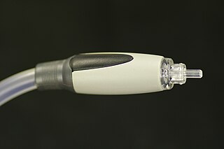
An optical fiber connector is a device used to link optical fibers, facilitating the efficient transmission of light signals. An optical fiber connector enables quicker connection and disconnection than splicing.
Multi-mode optical fiber is a type of optical fiber mostly used for communication over short distances, such as within a building or on a campus. Multi-mode links can be used for data rates up to 800 Gbit/s. Multi-mode fiber has a fairly large core diameter that enables multiple light modes to be propagated and limits the maximum length of a transmission link because of modal dispersion. The standard G.651.1 defines the most widely used forms of multi-mode optical fiber.

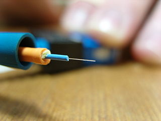
An optical fiber, or optical fibre, is a flexible glass or plastic fiber that can transmit light from one end to the other. Such fibers find wide usage in fiber-optic communications, where they permit transmission over longer distances and at higher bandwidths than electrical cables. Fibers are used instead of metal wires because signals travel along them with less loss and are immune to electromagnetic interference. Fibers are also used for illumination and imaging, and are often wrapped in bundles so they may be used to carry light into, or images out of confined spaces, as in the case of a fiberscope. Specially designed fibers are also used for a variety of other applications, such as fiber optic sensors and fiber lasers.

Fiber-optic communication is a method of transmitting information from one place to another by sending pulses of infrared or visible light through an optical fiber. The light is a form of carrier wave that is modulated to carry information. Fiber is preferred over electrical cabling when high bandwidth, long distance, or immunity to electromagnetic interference is required. This type of communication can transmit voice, video, and telemetry through local area networks or across long distances.

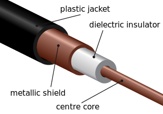
A fiber-optic cable, also known as an optical-fiber cable, is an assembly similar to an electrical cable but containing one or more optical fibers that are used to carry light. The optical fiber elements are typically individually coated with plastic layers and contained in a protective tube suitable for the environment where the cable is used. Different types of cable are used for fiber-optic communication in different applications, for example long-distance telecommunication or providing a high-speed data connection between different parts of a building.
An optical power meter (OPM) is a device used to measure the power in an optical signal. The term usually refers to a device for testing average power in fiber optic systems. Other general purpose light power measuring devices are usually called radiometers, photometers, laser power meters, light meters or lux meters.
Radio over fiber (RoF) or RF over fiber (RFoF) refers to a technology whereby light is modulated by a radio frequency signal and transmitted over an optical fiber link. Main technical advantages of using fiber optical links are lower transmission losses and reduced sensitivity to noise and electromagnetic interference compared to all-electrical signal transmission.
A fiber-optic sensor is a sensor that uses optical fiber either as the sensing element, or as a means of relaying signals from a remote sensor to the electronics that process the signals. Fibers have many uses in remote sensing. Depending on the application, fiber may be used because of its small size, or because no electrical power is needed at the remote location, or because many sensors can be multiplexed along the length of a fiber by using light wavelength shift for each sensor, or by sensing the time delay as light passes along the fiber through each sensor. Time delay can be determined using a device such as an optical time-domain reflectometer and wavelength shift can be calculated using an instrument implementing optical frequency domain reflectometry.
Wavelength selective switching components are used in WDM optical communications networks to route (switch) signals between optical fibres on a per-wavelength basis.
TOSLINK is a standardized optical fiber connector system. Generically known as optical audio, the most common use of the TOSLINK optical fiber connector is in consumer audio equipment in which the digital optical socket carries (transmits) a stream of digital audio signals from audio equipment to an AV receiver that can decode two channels of uncompressed, pulse-code modulated (PCM) audio; or decode compressed 5.1/7.1 surround sound audio signals, such as Dolby Digital and DTS. Unlike an HDMI connector cable, a TOSLINK optical fiber connector does not possess the bandwidth capacity to carry the uncompressed audio signals of Dolby TrueHD and of DTS-HD Master Audio; nor carry more than two channels of PCM audio.
A fiber-optic patch cord is a fiber-optic cable capped at each end with connectors that allow it to be rapidly and conveniently connected to telecommunication equipment. This is known as interconnect-style cabling.
A fiber-optic adapter connects two optical fiber connectors in the fiber optic lines.
