Nondestructive testing (NDT) is any of a wide group of analysis techniques used in science and technology industry to evaluate the properties of a material, component or system without causing damage. The terms nondestructive examination (NDE), nondestructive inspection (NDI), and nondestructive evaluation (NDE) are also commonly used to describe this technology. Because NDT does not permanently alter the article being inspected, it is a highly valuable technique that can save both money and time in product evaluation, troubleshooting, and research. The six most frequently used NDT methods are eddy-current, magnetic-particle, liquid penetrant, radiographic, ultrasonic, and visual testing. NDT is commonly used in forensic engineering, mechanical engineering, petroleum engineering, electrical engineering, civil engineering, systems engineering, aeronautical engineering, medicine, and art. Innovations in the field of nondestructive testing have had a profound impact on medical imaging, including on echocardiography, medical ultrasonography, and digital radiography.
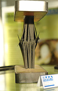
Delamination is a mode of failure where a material fractures into layers. A variety of materials including laminate composites and concrete can fail by delamination. Processing can create layers in materials such as steel formed by rolling and plastics and metals from 3D printing which can fail from layer separation. Also, surface coatings such as paints and films can delaminate from the coated substrate.
Acoustic emission (AE) is the phenomenon of radiation of acoustic (elastic) waves in solids that occurs when a material undergoes irreversible changes in its internal structure, for example as a result of crack formation or plastic deformation due to aging, temperature gradients or external mechanical forces. In particular, AE is occurring during the processes of mechanical loading of materials and structures accompanied by structural changes that generate local sources of elastic waves. This results in small surface displacements of a material produced by elastic or stress waves generated when the accumulated elastic energy in a material or on its surface is released rapidly. The waves generated by sources of AE are of practical interest in structural health monitoring (SHM), quality control, system feedback, process monitoring and other fields. In SHM applications, AE is typically used to detect, locate and characterise damage.
Eddy-current testing is one of many electromagnetic testing methods used in nondestructive testing (NDT) making use of electromagnetic induction to detect and characterize surface and sub-surface flaws in conductive materials.
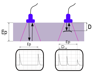
Ultrasonic testing (UT) is a family of non-destructive testing techniques based on the propagation of ultrasonic waves in the object or material tested. In most common UT applications, very short ultrasonic pulse-waves with center frequencies ranging from 0.1-15 MHz, and occasionally up to 50 MHz, are transmitted into materials to detect internal flaws or to characterize materials. A common example is ultrasonic thickness measurement, which tests the thickness of the test object, for example, to monitor pipework corrosion.

Time-of-flight diffraction (TOFD) method of ultrasonic testing is a sensitive and accurate method for the nondestructive testing of welds for defects. TOFD originated from tip diffraction techniques which were first published by Silk and Liddington in 1975 which paved the way for TOFD. Later works on this technique are given in a number of sources which include Harumi et al. (1989), Avioli et al. (1991), and Bray and Stanley (1997).
Electromagnetic testing (ET), as a form of nondestructive testing, is the process of inducing electric currents or magnetic fields or both inside a test object and observing the electromagnetic response. If the test is set up properly, a defect inside the test object creates a measurable response.

Rail inspection is the practice of examining rail tracks for flaws that could lead to catastrophic failures. According to the United States Federal Railroad Administration Office of Safety Analysis, track defects are the second leading cause of accidents on railways in the United States. The leading cause of railway accidents is attributed to human error. The contribution of poor management decisions to rail accidents caused by infrequent or inadequate rail inspection is significant but not reported by the FRA, only the NTSB. Every year, North American railroads spend millions of dollars to inspect the rails for internal and external flaws. Nondestructive testing (NDT) methods are used as preventive measures against track failures and possible derailment.
Internal rotary inspection system (IRIS) is an ultrasonic method for the nondestructive testing of pipes and tubes. The IRIS probe is inserted into a tube that is flooded with water, and the probe is pulled out slowly as the data is displayed and recorded. The ultrasonic beam allows detection of metal loss from the inside and outside of the tube wall.

Electromagnetic acoustic transducer (EMAT) is a transducer for non-contact acoustic wave generation and reception in conducting materials. Its effect is based on electromagnetic mechanisms, which do not need direct coupling with the surface of the material. Due to this couplant-free feature, EMATs are particularly useful in harsh, i.e., hot, cold, clean, or dry environments. EMATs are suitable to generate all kinds of waves in metallic and/or magnetostrictive materials. Depending on the design and orientation of coils and magnets, shear horizontal (SH) bulk wave mode, surface wave, plate waves such as SH and Lamb waves, and all sorts of other bulk and guided-wave modes can be excited. After decades of research and development, EMAT has found its applications in many industries such as primary metal manufacturing and processing, automotive, railroad, pipeline, boiler and pressure vessel industries, in which they are typically used for nondestructive testing (NDT) of metallic structures.
Thermographic inspection refers to the nondestructive testing (NDT) of parts, materials or systems through the imaging of the temperature fields, gradients and/or patterns ("thermograms") at the object's surface. It is distinguished from medical thermography by the subjects being examined: thermographic inspection generally examines inanimate objects, while medical thermography generally examines living organisms. Generally, thermographic inspection is performed using an infrared sensor.
Hot plate welding, also called heated tool welding, is a thermal welding technique for joining thermoplastics. A heated tool is placed against or near the two surfaces to be joined in order to melt them. Then, the heat source is removed, and the surfaces are brought together under pressure. Hot plate welding has relatively long cycle times, ranging from 10 seconds to minutes, compared to vibration or ultrasonic welding. However, its simplicity and ability to produce strong joints in almost all thermoplastics make it widely used in mass production and for large structures, like large-diameter plastic pipes. Different inspection techniques are implemented in order to identify various discontinuities or cracks.
Vidisco is an Israeli based developer and manufacturer of portable digital X-ray inspection systems.
Corrosion mapping by ultrasonics is a nonintrusive (noninvasive) technique which maps material thickness using ultrasonic techniques.
Shantou Institute of Ultrasonic Instruments Co., Ltd (SIUI) is China's biggest manufacturing base of ultrasound with longest history. SIUI goes through a technology development of A-B-C-D-E. Each step has driven the industry progress in China. A: A mode ultrasound equipment. B:B mode ultrasound imaging equipment. C:Color Doppler. In 1997, SIUI manufactured its first color Doppler system Apogee 800.D:Real-time 3D/4D ultrasound. In 2008, SIUI developed the real-time 3D/4D technology, and released a series of real-time 3D/ 4D color Doppler systems. E: Elastography.
Microwave imaging is a science which has been evolved from older detecting/locating techniques in order to evaluate hidden or embedded objects in a structure using electromagnetic (EM) waves in microwave regime. Engineering and application oriented microwave imaging for non-destructive testing is called microwave testing, see below.
Active thermography is an advanced nondestructive testing procedure, which uses a thermography measurement of a tested material thermal response after its external excitation. This principle can be used also for non-contact infrared non-destructive testing (IRNDT) of materials.
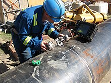
Robotic non-destructive testing (NDT) is a method of inspection used to assess the structural integrity of petroleum, natural gas, and water installations. Crawler-based robotic tools are commonly used for in-line inspection (ILI) applications in pipelines that cannot be inspected using traditional intelligent pigging tools.
Welding of advanced thermoplastic composites is a beneficial method of joining these materials compared to mechanical fastening and adhesive bonding. Mechanical fastening requires intense labor, and creates stress concentrations, while adhesive bonding requires extensive surface preparation, and long curing cycles. Welding these materials is a cost-effective method of joining concerning preparation and execution, and these materials retain their properties upon cooling, so no post processing is necessary. These materials are widely used in the aerospace industry to reduce weight of a part while keeping strength.
A variety of non-destructive examination (NDE) techniques are available for inspecting plastic welds. Many of these techniques are similar to the ones used for inspecting metal welds. Traditional techniques include visual testing, radiography, and various ultrasonic techniques. Advanced ultrasonic techniques such as time of flight diffraction (TOFD) and phased-array ultrasonics (PAUT) are being increasingly studied and used for inspecting plastic pipeline welds. Research in the use of optical coherence tomography (OCT) and microwave reflectrometry has also been conducted.