A typical mid-war Post Plotting Instrument. Note the two pointers on the map (near the dashed circle), indicating the addition of the Micklethwait Height Corrector.
The Post Plotting Instrument, or simply Post Instrument and sometimes the Observer Instrument, was the standard optical sighting system used by the UK's Royal Observer Corps (ROC) to determine the location of aircraft. It was used during the period from the mid-1930s into the early 1950s, and was one of the main sources of daytime tracking information during World War II.
There were two versions of the Post Instrument, a pre-war model using a pantograph, and a wartime version of somewhat more sophistication. Both required the operator to estimate the altitude of the aircraft and enter that into the device, then point a mechanical indicator, or sight, at the aircraft. The motion of the sight moved an indicator on a small Ordnance Survey National Grid map. The grid location indicated by the pointer was then telephoned to central control rooms, where several such reports were combined to produce a more accurate location estimate.
Later models added the Micklethwait Height Corrector, which allowed the posts to measure altitude with some accuracy and thus improve the quality of the measurements. The ROC also developed a methodology that allowed the Post Instrument to be used to produce measurements purely by sound, but it is unclear how often this was used.
Background
Prior to the introduction of radar, optical tracking systems of widely varying complexity were commonly used to spot and report aircraft positions. The Post Instrument was intended to be at the simple end of the scale, an inexpensive and easy to use instrument to make rough but rapid measurements of the locations of aircraft.[1]
Post Instruments were installed at hundreds of observation posts across the UK, typically in small groups of three or four posts about 3 to 5 miles (4.8 to 8.0km) apart. This spacing allowed the operators to cross check each other's altitude measurements. Each post was normally manned by two or three operators, one operating the Post Instrument, another using the telephone to report the locations to a plotting center, and the third, if present, operating as a lookout and helper.[2]
Pre-war model
The original Post Instrument was mounted on a metal rod extending vertically from the centre of a circular table. A small section of a map showing the surrounding area was attached to the tabletop.[1]
The instrument itself consisted of an open rectangle of metal bars, with the long axis horizontal. Hinges at the connection points between the bars allowed the bars to be rotated to form various parallelograms. Similar hinges were located at the midpoints of the long horizontal bars of the rectangle. These midpoint pivots connected to the vertical bar on the table. The result was a pantograph that allowed the long horizontal bars to be rotated into the vertical to point upward at an aircraft, sighting along the upper bar.[1]
A final piece was a separate vertical bar connected to the two horizontals and pivoted in the same way so that it remained pointing vertically as the horizontal bars were rotated. This bar was able to be moved along the horizontal bars, fore and aft, which was used to adjust the estimated altitude.[1]
To use the system, the operator would first estimate the altitude of the target aircraft and then move the smaller pointer to that altitude as measured against a scale on the upper horizontal arm. They would then rotate the apparatus around the vertical shaft so the target aircraft lay along the line of the upper bar and then rotate the bar vertically until it pointed at the aircraft. The vertical pointer now pointed to a grid location on the map, which could be read off to the reporting centre.[1]
Wartime model
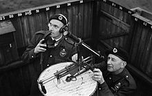
The RAF Museum's Post Instrument is typical of early wartime examples. This model appears to be built in 1936.
The original model worked but was somewhat difficult and time consuming to use. Just prior to the war a new version was introduced that was easier to use. Officially known as the Observer Instrument, Mark 2, the first examples were built by R.B. Pullin & Co., starting in 1934.[2]
The vertical rod of the original version was replaced by a horizontal framework, roughly T-shaped, that was suspended above the table on three wheels running on a metal track around the rim of the map. This provided a much more robust framework for holding the sighting system, and rotated much more smoothly. A pointer behind the front wheel made it easy to read off the bearing, when required. Travelling along the framework horizontally fore and aft was a sliding mechanism that held the sights. This formed the altitude adjustment that would be set prior to sighting. The map pointer was connected to the bottom of the slider.[3]
The sights, in the form of an open-framework tube containing a crosshairs, was mounted to the horizontal slider on a vertical square tube. Sightings could be taken either through the crosshairs or along open sights on the top of the tube.[4] A geared rack running down the back of the tube held the sights at a selected angle, and the angle was adjusted by rotating a geared knob on the right side of the sights. As the sights were rotated upwards, they forced the horizontal slider to the rear, moving the pointer over the map.[3]
Micklethwait Height Corrector
Wartime models were modified in 1940 with the Micklethwait Height Corrector, named for its inventor, Eric Walter Eustace Micklethwait. Micklethwait was an observer at the Gower Street Post on the roof of a building at University of London, near Euston Square tube station. Formerly a patent clerk, he devised the Corrector and quickly patented it.[5]
The Corrector consisted of a second map pointer on a second horizontal slider, with a crank that moved the horizontal slider fore and aft. A second arm suspended from the main sight tube was pushed up and down as the horizontal portion slid. This arm was measured against a short vertical bar marked with altitude corrections. The system indicated only corrections, not the actual altitude. Two or more posts had to work in concert to use the system, using two measured angles and simple trigonometry to solve the altitude.[3]
The simplest measurement took place when an aircraft flew directly over one of the posts. Other posts that could see the same aircraft would continue to track the target as normal, set to whatever altitude they had initially estimated. When the first post called that the aircraft was directly overhead, the other posts would crank the Corrector until its pointer lay over a marking for the other post printed on the map.[6]
For instance, if the original estimate was 10,000 feet (3,000m) and the aircraft was actually at 11,000 feet (3,400m), the operator at a second post would set his instrument to 10,000 and continue to measure as normal until they heard the first post call "aircraft overhead". At this point they would stop measuring the aircraft and instead crank the Corrector until its pointer lay over the marking on the map indicating the location of the first post. By comparing the position of the bar suspended from the sighting tube to the Corrector's vertical scale, they would see it indicate +1000. This correction was called to the ROC center who then forwarded it to all the posts in the area to update their altitude settings to 11,000 feet.[6]
When the target did not pass directly over a post the calculation was somewhat more complex. In this case two posts would measure the location of the aircraft at the same time, and then one would call the aircraft's measured grid reference to the other. The second would then place a ruler on the map lying along the line from their measured location on the map to the one called in from the other post. They would then crank the Corrector until its pointer lay directly above the nearest point on the ruler, and the correction could then be read off as normal.[7]
An alternate procedure involved the use of an operator at the observer center. Gathering indicated grid locations from several sites set to the same arbitrary altitude, they would triangulate the grid location of the target and pass this information back to the posts. The operators at the posts would then crank the Corrector until its pointer lay over the calculated grid location, at which point the correction could be read.[5]
Sound measures
The Post Instrument was introduced in an era when sound locating was still common, and some techniques for measuring the angle by sound were developed. This basically consisted of moving the horizontal slider until the indicator pointer was over the "sound line", a circle on the map representing a 5 miles (8.0km) distance around the post. The operator would then rotate the sights horizontally and vertically to try to point the sights in the direction they estimated the sound to be coming from. Instead of using the map, the operator instead called the horizontal and vertical angles to their operations room. The horizontal angle could be read off a scale around the outer edge of the map, but the vertical angle was instead measured by dropping the last three zeros of the altitude measurement, so if the sights were over the 14,000 foot marker, they would call in "angle 14".[8][9][lower-alpha 1]
In the operations room, a plotter trained in sound measurements would take the angle measurements from multiple stations and determine the location by plotting the angles on a map and looking for the intersections. They would then calculate the distance from one or more of the posts and calculate the altitude using the formula altitude = angle x calculated distance ÷ 5. For instance, if they found that the aircraft was 4 miles (6.4km) from a particular post that indicated the angle was 14, then the altitude would be 14 x 4 / 5 = 56/5 = about 11,000 feet. Plotters were equipped with pre-calculated tables to make these calculations quickly.[8][10]
Reporting system
A Centre 'Ops Room': Tellers on the balcony overlook the plotting table and vertical long-range handover board. At the end of the balcony a Leading Observer acts as Post Controller.Details of the plotting map and long-range board. The sector clock on the wall was used to select colors for the markers being placed on the map, indicating the age of the report.
The Observer Corp was an expansion of a system originally set up in World War I to coordinate the reports from observers in the London area, part of the London Air Defence Area (LADA). In this system, originally set up by Edward Ashmore, observers telephoned reports of aircraft to a plotting center in the Horse Guards building in London. Information from the map would then be forwarded to the searchlights and anti-aircraft guns in the LADA area.[11]
In the post-World War I era the system was taken over by the Air Defence of Great Britain organization, formally part of the Royal Air Force but containing British Army and Royal Engineer units as well. It was re-organized and expanded, covering not only the London area but adding similar reporting organizations in The Midlands. They also introduced new techniques to deal with faster aircraft.[12]
In the new systems, plotters would take the reports from the observers and place a colored marker on a large map inside the indicated grid location. The marker held information about the number and altitude of the aircraft. The marker colors changed every five minutes, based on a sector clock, and when the marker was moved to a new location, a smaller marker was left behind in its former location. This produced a trail of colored markers on the map that allowed observers to easily see the track of the aircraft, as well as estimate how quickly it was moving.[13]
The Dowding system was built on top of this reporting system. It added a central filter room that acted as a plotting station for all of the Chain Home radar stations. Reports from the filter room were then forwarded to Group plotting rooms where they were combined with information from the Observer Corps. The same basic system using colored markers indicating the time, altitude and number of aircraft was used throughout the system.[14] Just prior to the war, two additional Groups were added to cover Scotland and the north, and the southwest.
Starting in 1942, additional charts were installed at the Group plotting centers that allowed information from neighbouring Groups to be recorded. This was useful for handing over tracks that were moving across Group boundaries.[14]
Notes
↑ The Post Instrument included a separate scale for measuring vertical angles, which can be seen in the images. This scale is very small, and offers limited accuracy.
Related Research Articles
Surveying or land surveying is the technique, profession, art, and science of determining the terrestrial two-dimensional or three-dimensional positions of points and the distances and angles between them. A land surveying professional is called a land surveyor. These points are usually on the surface of the Earth, and they are often used to establish maps and boundaries for ownership, locations, such as the designed positions of structural components for construction or the surface location of subsurface features, or other purposes required by government or civil law, such as property sales.
Celestial navigation, also known as astronavigation, is the practice of position fixing using stars and other celestial bodies that enables a navigator to accurately determine their actual current physical position in space or on the surface of the Earth without relying solely on estimated positional calculations, commonly known as "dead reckoning." Celestial navigation is performed without using satellite navigation or other similar modern electronic or digital positioning means.
Indirect fire is aiming and firing a projectile without relying on a direct line of sight between the gun and its target, as in the case of direct fire. Aiming is performed by calculating azimuth and inclination, and may include correcting aim by observing the fall of shot and calculating new angles.
A theodolite is a precision optical instrument for measuring angles between designated visible points in the horizontal and vertical planes. The traditional use has been for land surveying, but it is also used extensively for building and infrastructure construction, and some specialized applications such as meteorology and rocket launching.
An automatic direction finder (ADF) is a marine or aircraft radio-navigation instrument that automatically and continuously displays the relative bearing from the ship or aircraft to a suitable radio station. ADF receivers are normally tuned to aviation or marine NDBs operating in the LW band between 190 – 535 kHz. Like RDF units, most ADF receivers can also receive medium wave (AM) broadcast stations, though these are less reliable for navigational purposes.
Chain Home, or CH for short, was the codename for the ring of coastal early warning radar stations built by the Royal Air Force (RAF) before and during the Second World War to detect and track aircraft. Initially known as RDF, and given the official name Air Ministry Experimental Station Type 1 in 1940, the radar units were also known as Chain Home for most of their life. Chain Home was the first early warning radar network in the world and the first military radar system to reach operational status. Its effect on the war made it one of the most powerful weapons of what became known as the "Wizard War".
An alidade or a turning board is a device that allows one to sight a distant object and use the line of sight to perform a task. This task can be, for example, to triangulate a scale map on site using a plane table drawing of intersecting lines in the direction of the object from two or more points or to measure the angle and horizontal distance to the object from some reference point's polar measurement. Angles measured can be horizontal, vertical or in any chosen plane.
A total station (TS) or total station theodolite (TST) is an electronic/optical instrument used for surveying and building construction. It is an electronic transit theodolite integrated with electronic distance measurement (EDM) to measure both vertical and horizontal angles and the slope distance from the instrument to a particular point, and an on-board computer to collect data and perform triangulation calculations.
Levelling or leveling is a branch of surveying, the object of which is to establish or verify or measure the height of specified points relative to a datum. It is widely used in geodesy and cartography to measure vertical position with respect to a vertical datum, and in construction to measure height differences of construction artifacts.
A nephoscope is a 19th-century instrument for measuring the altitude, direction, and velocity of clouds, using transit-time measurement. This is different from a nephometer, which is an instrument used in measuring the amount of cloudiness.
Gun laying is the process of aiming an artillery piece or turret, such as a gun, howitzer, or mortar, on land, in air, or at sea, against surface or aerial targets. It may be laying for direct fire, where the gun is aimed similarly to a rifle, or indirect fire, where firing data is calculated and applied to the sights. The term includes automated aiming using, for example, radar-derived target data and computer-controlled guns.
A level is an optical instrument used to establish or verify points in the same horizontal plane in a process known as levelling. It is used in conjunction with a levelling staff to establish the relative height or levels of objects or marks. It is widely used in surveying and construction to measure height differences and to transfer, measure, and set heights of known objects or marks.
Tacheometry is a system of rapid surveying, by which the horizontal and vertical positions of points on the earth's surface relative to one another are determined without using a chain or tape, or a separate levelling instrument. Instead of the pole normally employed to mark a point, a staff similar to a level staff is used. This is marked with heights from the base or foot, and is graduated according to the form of tacheometer in use.
A bombsight is a device used by military aircraft to drop bombs accurately. Bombsights, a feature of combat aircraft since World War I, were first found on purpose-designed bomber aircraft and then moved to fighter-bombers and modern tactical aircraft as those aircraft took up the brunt of the bombing role.
A radar display is an electronic device that presents radar data to the operator. The radar system transmits pulses or continuous waves of electromagnetic radiation, a small portion of which backscatter off targets and return to the radar system. The receiver converts all received electromagnetic radiation into a continuous electronic analog signal of varying voltage that can be converted then to a screen display.
The Stabilised Automatic Bomb Sight (SABS) was a Royal Air Force bombsight used in small numbers during World War II. The system worked along similar tachometric principles as the more famous Norden bombsight, but was somewhat simpler, lacking the Norden's autopilot feature.
The Mark XIV Bomb Sight was a bombsight developed by Royal Air Force (RAF) Bomber Command during the Second World War. It was also known as the Blackett sight after its primary inventor, P. M. S. Blackett. Production of a slightly modified version was also undertaken in the United States as the Sperry T-1, which was interchangeable with the UK-built version. It was the RAF's standard bombsight for the second half of the war.
The Dumaresq is a mechanical calculating device invented around 1902 by Lieutenant John Dumaresq of the Royal Navy. It is a computer that relates vital variables of the fire control problem to the movement of one's own ship and that of a target ship.
In the U.S. Army Coast Artillery Corps, the term fire control system was used to refer to the personnel, facilities, technology and procedures that were used to observe designated targets, estimate their positions, calculate firing data for guns directed to hit those targets, and assess the effectiveness of such fire, making corrections where necessary.
The Course Setting Bomb Sight (CSBS) is the canonical vector bombsight, the first practical system for properly accounting for the effects of wind when dropping bombs. It is also widely referred to as the Wimperis sight after its inventor, Harry Wimperis.
This page is based on this Wikipedia article Text is available under the CC BY-SA 4.0 license; additional terms may apply. Images, videos and audio are available under their respective licenses.