Ordnance Survey National Grid

Last updated

The Ordnance Survey National Grid reference system (OSGB) (also known as British National Grid (BNG) [1] [2] ) is a system of geographic grid references used in Great Britain, distinct from latitude and longitude.

Contents

The Ordnance Survey (OS) devised the national grid reference system, and it is heavily used in its survey data, and in maps based on those surveys, whether published by the Ordnance Survey or by commercial map producers. Grid references are also commonly quoted in other publications and data sources, such as guide books and government planning documents.

A number of different systems exist that can provide grid references for locations within the British Isles: this article describes the system created solely for Great Britain and its outlying islands (including the Isle of Man); the Irish grid reference system was a similar system created by the Ordnance Survey of Ireland and the Ordnance Survey of Northern Ireland for the island of Ireland. The Universal Transverse Mercator coordinate system (UTM) is used to provide grid references for worldwide locations, and this is the system commonly used for the Channel Islands and Ireland (since 2001). European-wide agencies also use UTM when mapping locations, or may use the Military Grid Reference System (MGRS), or variants of it.

Grid letters

100km squares British National Grid.svg
100km squares
Grid square TF. The map shows The Wash and the North Sea, as well as places within the counties of Lincolnshire, Cambridgeshire and Norfolk. Ordnance Survey 1-250000 - TF.jpg
Grid square TF. The map shows The Wash and the North Sea, as well as places within the counties of Lincolnshire, Cambridgeshire and Norfolk.

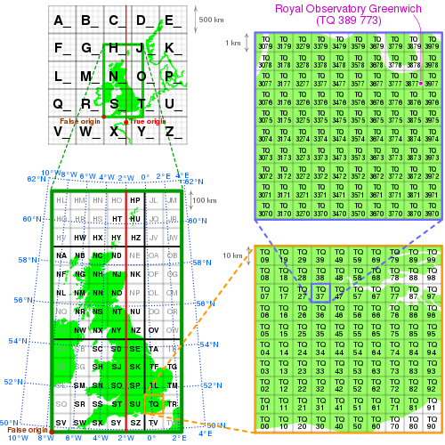
The first letter of the British National Grid is derived from a larger set of 25 squares of size 500 km by 500 km, labelled A to Z, omitting one letter (I) (refer diagram below), previously used as a military grid. [3] Four of these largest squares contain significant land area within Great Britain: S, T, N and H. The O square contains a tiny area of North Yorkshire, Beast Cliff at OV 0000 , almost all of which lies below mean high tide. [4] For the second letter, each 500 km square is subdivided into 25 squares of size 100 km by 100 km, each with a letter code from A to Z (again omitting I) starting with A in the north-west corner to Z in the south-east corner. These squares are outlined in light grey on the "100km squares" map, with those containing land lettered. The central (2° W) meridian is shown in red.

Grid digits

Within each square, eastings and northings from the south west corner of the square are given numerically. For example, NH0325 means a 1 km square whose south-west corner is 3 km east and 25 km north from the south-west corner of square NH. A location can be indicated to varying resolutions numerically, usually from two digits in each coordinate (for a 1 km square) through to five (for a 1 m square); in each case the first half of the digits is for the first coordinate and the second half for the other. The most common usage is the six figure grid reference, employing three digits in each coordinate to determine a 100 m square. For example, the grid reference of the 100 m square containing the summit of Ben Nevis is NN 166 712 . (Grid references may be written with or without spaces; e.g., also NN166712.) NN has an easting of 200 km and northing of 700 km, so the OSGB36 National Grid location for Ben Nevis is at 216600, 771200.

Illustration of the Ordnance Survey National Grid coordinate system, with Royal Observatory Greenwich as an example Ordnance Survey National Grid.svg
Illustration of the Ordnance Survey National Grid coordinate system, with Royal Observatory Greenwich as an example

All-numeric grid references

Grid references may also be quoted as a pair of numbers: eastings then northings in metres, measured from the southwest corner of the SV square. 14 digits may be required for locations in Orkney and further north. For example, the grid reference for Sullom Voe oil terminal in the Shetland Islands may be given as HU396753 or 439668,1175316.

Another, distinct, form of all-numeric grid reference is an abbreviated alphanumeric reference where the letters are simply omitted, e.g. 166712 for the summit of Ben Nevis. Unlike the numeric references described above, this abbreviated grid reference is incomplete; it gives the location relative to an OS 100×100 km square, but does not specify which square. It is often used informally when the context identifies the OS 2-letter square. For example, within the context of a location known to be on OS Landranger sheet 41 (which extends from NN000500 in the south-west to NN400900 in the north-east) the abbreviated grid reference 166712 is equivalent to NN166712. If working with more than one Landranger sheet, this may also be given as 41/166712.

Alternatively, sometimes numbers instead of the two-letter combinations are used for the 100×100 km squares. The numbering follows a grid index where the tens denote the progress from West to East and the units from South to North. In the north of Scotland, the numbering is modified: the 100 km square to the north of 39 is numbered N30; the square to the north of 49 is N40, etc.

The grid is based on the OSGB36 datum (Ordnance Survey Great Britain 1936, based on the Airy 1830 ellipsoid), and was introduced after the retriangulation of 1936–1962.[ citation needed ] It replaced the Cassini Grid which had previously been the standard projection for Ordnance Survey maps. [5] [6]

The Airy ellipsoid is a regional best fit for Britain; more modern mapping tends to use the GRS80 ellipsoid used by the Global Positioning System (the Airy ellipsoid assumes the Earth to be about 1 km smaller in diameter than the GRS80 ellipsoid, and to be slightly less flattened). The British maps adopt a transverse Mercator projection with an origin (the "true" origin) at 49° N,  W (an offshore point in the English Channel which lies between the island of Jersey and the French port of St. Malo). [7] Over the Airy ellipsoid a straight line grid, the National Grid, is placed with a new false origin to eliminate negative numbers, creating a 700 km by 1300 km grid. This false origin is located south-west of the Isles of Scilly.

In order to minimize the overall scale error, a factor of 2499/2500 is applied. This creates two lines of longitude about 180 km east and west of the central meridian along which the local scale factor equals 1, i.e. map scale is correct. Inside these lines the local scale factor is less than 1, with a minimum of 0.04% too small at the central meridian. [8] Outside these lines the local scale factor is greater than 1, and is about 0.04% too large near the east and west coasts. Grid north and true north are only aligned on the central meridian (400 km easting) of the grid which is 2° W (OSGB36) and approx. 2° 0′ 5″ W (WGS 84).

OSGB 36 was also used by Admiralty nautical charts until 2000[ citation needed ] after which WGS 84 has been used.

A geodetic transformation between OSGB 36 and other terrestrial reference systems (like ITRF2000, ETRS89, or WGS 84) can become quite tedious if attempted manually. The most common transformation is called the Helmert datum transformation, which results in a typical 7 m error from true. The definitive transformation from ETRS89 that is published by the Ordnance Survey is called the National Grid Transformation OSTN15. [9] [10] This models the detailed distortions in the 1936–1962 retriangulation, and achieves backwards compatibility in grid coordinates to sub-metre accuracy.

Datum shift between OSGB 36 and WGS 84

The difference between the coordinates on different datums varies from place to place. The longitude and latitude positions on OSGB 36 are the same as for WGS 84 at a point in the Atlantic Ocean well to the west of Great Britain. In Cornwall, the WGS 84 longitude lines are about 70 metres east of their OSGB 36 equivalents, this value rising gradually to about 120 m east on the east coast of East Anglia. The WGS 84 latitude lines are about 70 m south of the OSGB 36 lines in South Cornwall, the difference diminishing to zero in the Scottish Borders, and then increasing to about 50 m north on the north coast of Scotland. (If the lines are further east, then the longitude value of any given point is further west. Similarly, if the lines are further south, the values will give the point a more northerly latitude.) The smallest datum shift is on the west coast of Scotland and the greatest in Kent.

Datum shift between OSGB 36 and ED 50

These two datums are not both in general use in any one place, but for a point in the English Channel halfway between Dover and Calais, the ED50 longitude lines are about 20 m east of the OSGB36 equivalents, and the ED50 latitude lines are about 150 m south of the OSGB36 ones.[ citation needed ]

Summary parameters of the coordinate system

See also

Custom units of measure

Notes

  1. Scale factor is defined by its base-10 logarithm of (0.9998268 − 1) exactly. [11]
  2. The defining Airy dimensions are a 20923713 feet, b 20853810 feet. In the Retriangulation the base-10 logarithm of the number of metres in a foot was set at (0.48401603 − 1) [12] exactly and the Airy metric dimensions are calculated from that. The flattening is exactly 69903 divided by 20923713.

Related Research Articles

<span class="mw-page-title-main">Latitude</span> Geographic coordinate specifying north–south position

In geography, latitude is a coordinate that specifies the north–south position of a point on the surface of the Earth or another celestial body. Latitude is given as an angle that ranges from –90° at the south pole to 90° at the north pole, with 0° at the Equator. Lines of constant latitude, or parallels, run east–west as circles parallel to the equator. Latitude and longitude are used together as a coordinate pair to specify a location on the surface of the Earth.

<span class="mw-page-title-main">Geographic coordinate system</span> System to specify locations on Earth

The geographic coordinate system (GCS) is a spherical or geodetic coordinate system for measuring and communicating positions directly on the Earth as latitude and longitude. It is the simplest, oldest and most widely used of the various spatial reference systems that are in use, and forms the basis for most others. Although latitude and longitude form a coordinate tuple like a cartesian coordinate system, the geographic coordinate system is not cartesian because the measurements are angles and are not on a planar surface.

<span class="mw-page-title-main">Projected coordinate system</span> Cartesian geographic coordinate system

A projected coordinate system – also called a projected coordinate reference system, planar coordinate system, or grid reference system – is a type of spatial reference system that represents locations on Earth using Cartesian coordinates (x, y) on a planar surface created by a particular map projection. Each projected coordinate system, such as "Universal Transverse Mercator WGS 84 Zone 26N," is defined by a choice of map projection (with specific parameters), a choice of geodetic datum to bind the coordinate system to real locations on the earth, an origin point, and a choice of unit of measure. Hundreds of projected coordinate systems have been specified for various purposes in various regions.

<span class="mw-page-title-main">World Geodetic System</span> Geodetic reference system

The World Geodetic System (WGS) is a standard used in cartography, geodesy, and satellite navigation including GPS. The current version, WGS 84, defines an Earth-centered, Earth-fixed coordinate system and a geodetic datum, and also describes the associated Earth Gravitational Model (EGM) and World Magnetic Model (WMM). The standard is published and maintained by the United States National Geospatial-Intelligence Agency.

In geodesy, conversion among different geographic coordinate systems is made necessary by the different geographic coordinate systems in use across the world and over time. Coordinate conversion is composed of a number of different types of conversion: format change of geographic coordinates, conversion of coordinate systems, or transformation to different geodetic datums. Geographic coordinate conversion has applications in cartography, surveying, navigation and geographic information systems.

<span class="mw-page-title-main">Transverse Mercator projection</span> Adaptation of the standard Mercator projection

The transverse Mercator map projection is an adaptation of the standard Mercator projection. The transverse version is widely used in national and international mapping systems around the world, including the Universal Transverse Mercator. When paired with a suitable geodetic datum, the transverse Mercator delivers high accuracy in zones less than a few degrees in east-west extent.

<span class="mw-page-title-main">Geodetic datum</span> Reference frame for measuring location

A geodetic datum or geodetic system is a global datum reference or reference frame for precisely representing the position of locations on Earth or other planetary bodies by means of geodetic coordinates. Datums are crucial to any technology or technique based on spatial location, including geodesy, navigation, surveying, geographic information systems, remote sensing, and cartography. A horizontal datum is used to measure a location across the Earth's surface, in latitude and longitude or another coordinate system; a vertical datum is used to measure the elevation or depth relative to a standard origin, such as mean sea level (MSL). Since the rise of the global positioning system (GPS), the ellipsoid and datum WGS 84 it uses has supplanted most others in many applications. The WGS 84 is intended for global use, unlike most earlier datums.

<span class="mw-page-title-main">European Terrestrial Reference System 1989</span> Geodetic reference frame fixed to the Eurasian Plate

The European Terrestrial Reference System 1989 (ETRS89) is an ECEF geodetic Cartesian reference frame, in which the Eurasian Plate as a whole is static. The coordinates and maps in Europe based on ETRS89 are not subject to change due to the continental drift.

<span class="mw-page-title-main">Irish grid reference system</span> System of geographic grid references used for mapping in Ireland

The Irish grid reference system is a system of geographic grid references used for paper mapping in Ireland. The Irish grid partially overlaps the British grid, and uses a similar co-ordinate system but with a meridian more suited to its westerly location.

<span class="mw-page-title-main">Military Grid Reference System</span> NATO global coordinate reference system

The Military Grid Reference System (MGRS) is the geocoordinate standard used by NATO militaries for locating points on Earth. The MGRS is derived from the Universal Transverse Mercator (UTM) grid system and the Universal Polar Stereographic (UPS) grid system, but uses a different labeling convention. The MGRS is used as geocode for the entire Earth.

The Swiss coordinate system is a geographic coordinate system used in Switzerland and Liechtenstein for maps and surveying by the Swiss Federal Office of Topography (Swisstopo).

<span class="mw-page-title-main">ED50</span> Reference frame for European geodesy

ED50 is a geodetic datum which was defined after World War II for the international connection of geodetic networks.

<span class="mw-page-title-main">Universal Transverse Mercator coordinate system</span> System for assigning planar coordinates to locations on the surface of the Earth.

The Universal Transverse Mercator (UTM) is a map projection system for assigning coordinates to locations on the surface of the Earth. Like the traditional method of latitude and longitude, it is a horizontal position representation, which means it ignores altitude and treats the earth surface as a perfect ellipsoid. However, it differs from global latitude/longitude in that it divides earth into 60 zones and projects each to the plane as a basis for its coordinates. Specifying a location means specifying the zone and the x, y coordinate in that plane. The projection from spheroid to a UTM zone is some parameterization of the transverse Mercator projection. The parameters vary by nation or region or mapping system.

<span class="mw-page-title-main">Spatial reference system</span> System to specify locations on Earth

A spatial reference system (SRS) or coordinate reference system (CRS) is a framework used to precisely measure locations on the surface of Earth as coordinates. It is thus the application of the abstract mathematics of coordinate systems and analytic geometry to geographic space. A particular SRS specification comprises a choice of Earth ellipsoid, horizontal datum, map projection, origin point, and unit of measure. Thousands of coordinate systems have been specified for use around the world or in specific regions and for various purposes, necessitating transformations between different SRS.

<span class="mw-page-title-main">North American Datum</span> Reference frame for geodesy on the continent

The North American Datum (NAD) is the horizontal datum now used to define the geodetic network in North America. A datum is a formal description of the shape of the Earth along with an "anchor" point for the coordinate system. In surveying, cartography, and land-use planning, two North American Datums are in use for making lateral or "horizontal" measurements: the North American Datum of 1927 (NAD 27) and the North American Datum of 1983 (NAD 83). Both are geodetic reference systems based on slightly different assumptions and measurements.

<span class="mw-page-title-main">Earth-centered, Earth-fixed coordinate system</span> 3-D coordinate system centered on the Earth

The Earth-centered, Earth-fixed coordinate system, also known as the geocentric coordinate system, is a cartesian spatial reference system that represents locations in the vicinity of the Earth as X, Y, and Z measurements from its center of mass. Its most common use is in tracking the orbits of satellites and in satellite navigation systems for measuring locations on the surface of the Earth, but it is also used in applications such as tracking crustal motion.

<span class="mw-page-title-main">Helmert transformation</span> Transformation method within a three-dimensional space

The Helmert transformation is a geometric transformation method within a three-dimensional space. It is frequently used in geodesy to produce datum transformations between datums. The Helmert transformation is also called a seven-parameter transformation and is a similarity transformation.

<span class="mw-page-title-main">Earth ellipsoid</span> Shape of planet Earth

An Earth ellipsoid or Earth spheroid is a mathematical figure approximating the Earth's form, used as a reference frame for computations in geodesy, astronomy, and the geosciences. Various different ellipsoids have been used as approximations.

Transverse Mercator projection has many implementations. Louis Krüger in 1912 developed one of his two implementations that expressed as a power series in the longitude difference from the central meridian. These series were recalculated by Lee in 1946, by Redfearn in 1948, and by Thomas in 1952. They are often referred to as the Redfearn series, or the Thomas series. This implementation is of great importance since it is widely used in the U.S. State Plane Coordinate System, in national and also international mapping systems, including the Universal Transverse Mercator coordinate system (UTM). They are also incorporated into the Geotrans coordinate converter made available by the United States National Geospatial-Intelligence Agency. When paired with a suitable geodetic datum, the series deliver high accuracy in zones less than a few degrees in east-west extent.

<span class="mw-page-title-main">Web Mercator projection</span> Mercator variant map projection

Web Mercator, Google Web Mercator, Spherical Mercator, WGS 84 Web Mercator or WGS 84/Pseudo-Mercator is a variant of the Mercator map projection and is the de facto standard for Web mapping applications. It rose to prominence when Google Maps adopted it in 2005. It is used by virtually all major online map providers, including Google Maps, CARTO, Mapbox, Bing Maps, OpenStreetMap, Mapquest, Esri, and many others. Its official EPSG identifier is EPSG:3857, although others have been used historically.

References

  1. "OSGB 1936 / British National Grid: EPSG Projection -- Spatial Reference". spatialreference.org. Archived from the original on 10 March 2016. Retrieved 9 March 2016.
  2. "Coordinate systems and projections for beginners". 26 March 2012. Archived from the original on 26 October 2021. Retrieved 19 September 2021.
  3. http://www.ordnancesurvey.co.uk: Guide to the National Grid, page 9 (archived version, May 2006)
  4. Standing, Peter (2006). "OV0000 a unique grid square at Beast Cliff". Geograph Project. Archived from the original on 1 November 2017. Retrieved 11 June 2007.
  5. Winterbotham, Harold St. John Loyd (1925). "Ordnance Survey of Scotland "Popular" Edition. One-inch map". The Geographical Journal. 65 (2): 160–162. doi:10.2307/1782246. JSTOR   1782246.
  6. Steers, James Alfred (1965). An Introduction to the Study of Map Projections (15 ed.). University of London Press. p. 229.
  7. OS Net, The true origin
  8. Ordnance Survey (1946). "A brief description of the National Grid and reference system". London: His Majesty's Stationery Office. p. 4.
  9. Greaves, Mark (2016). "OSGM15 and OSTN15: Updated transformations for UK and Ireland" (PDF). Geomatics World. Archived (PDF) from the original on 14 August 2022. Retrieved 5 October 2021.
  10. "Surveying guidelines". Ordnance Survey. Archived from the original on 18 July 2017.
  11. Mugnier, Clifford (October 2003). "Grids and Datums, United Kingdom" (PDF). p. 1095. Archived (PDF) from the original on 4 October 2022. Retrieved 19 February 2022.
  12. A guide to coordinate systems in Great Britain (see External links), footnote 10 on page 44