This article includes a list of general references, but it lacks sufficient corresponding inline citations .(October 2021) |
A process flow diagram (PFD) is a diagram commonly used in chemical and process engineering to indicate the general flow of plant processes and equipment. The PFD displays the relationship between major equipment of a plant facility and does not show minor details such as piping details and designations. Another commonly used term for a PFD is processflowsheet. It is the key document in process design. [1] Short description|Diagram used in process engineering}}
This article includes a list of general references, but it lacks sufficient corresponding inline citations .(October 2021) |
A process flow diagram (PFD) is a diagram commonly used in chemical and process engineering to indicate the general flow of plant processes and equipment. The PFD displays the relationship between major equipment of a plant facility and does not show minor details such as piping details and designations. Another commonly used term for a PFD is processflowsheet. It is the key document in process design. [2]
Typically, process flow diagrams of a single unit process include the following:
Process flow diagrams generally do not include:
Process flow diagrams of multiple process units within a large industrial plant will usually contain less detail and may be called block flow diagrams or schematic flow diagrams.
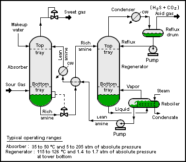
The process flow diagram below depicts a single chemical engineering unit process known as an amine treating plant:
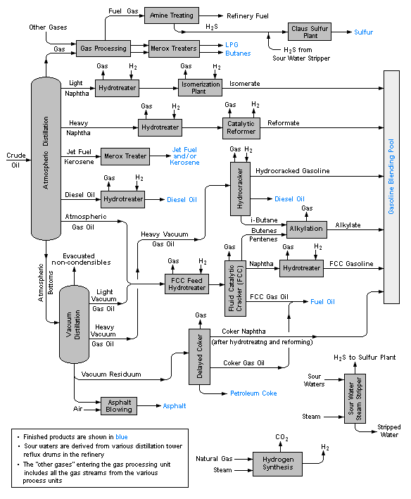
The process flow diagram below is an example of a schematic or block flow diagram and depicts the various unit processes within a typical oil refinery:
A PFD can be computer generated from process simulators (see List of Chemical Process Simulators), CAD packages, or flow chart software using a library of chemical engineering symbols. Rules and symbols are available from standardization organizations such as DIN, ISO or ANSI. Often PFDs are produced on large sheets of paper.
PFDs of many commercial processes can be found in the literature, specifically in encyclopedias of chemical technology, although some might be outdated. To find recent ones, patent databases such as those available from the United States Patent and Trademark Office can be useful.
Chemical engineering is an engineering field which deals with the study of operation and design of chemical plants as well as methods of improving production. Chemical engineers develop economical commercial processes to convert raw materials into useful products. Chemical engineering uses principles of chemistry, physics, mathematics, biology, and economics to efficiently use, produce, design, transport and transform energy and materials. The work of chemical engineers can range from the utilization of nanotechnology and nanomaterials in the laboratory to large-scale industrial processes that convert chemicals, raw materials, living cells, microorganisms, and energy into useful forms and products. Chemical engineers are involved in many aspects of plant design and operation, including safety and hazard assessments, process design and analysis, modeling, control engineering, chemical reaction engineering, nuclear engineering, biological engineering, construction specification, and operating instructions.
Instrumentation is a collective term for measuring instruments, used for indicating, measuring, and recording physical quantities. It is also a field of study about the art and science about making measurement instruments, involving the related areas of metrology, automation, and control theory. The term has its origins in the art and science of scientific instrument-making.
A flowchart is a type of diagram that represents a workflow or process. A flowchart can also be defined as a diagrammatic representation of an algorithm, a step-by-step approach to solving a task.
Process engineering is the understanding and application of the fundamental principles and laws of nature that allow humans to transform raw material and energy into products that are useful to society, at an industrial level. By taking advantage of the driving forces of nature such as pressure, temperature and concentration gradients, as well as the law of conservation of mass, process engineers can develop methods to synthesize and purify large quantities of desired chemical products. Process engineering focuses on the design, operation, control, optimization and intensification of chemical, physical, and biological processes. Process engineering encompasses a vast range of industries, such as agriculture, automotive, biotechnical, chemical, food, material development, mining, nuclear, petrochemical, pharmaceutical, and software development. The application of systematic computer-based methods to process engineering is "process systems engineering".
An industrial process control or simply process control in continuous production processes is a discipline that uses industrial control systems and control theory to achieve a production level of consistency, economy and safety which could not be achieved purely by human manual control. It is implemented widely in industries such as automotive, mining, dredging, oil refining, pulp and paper manufacturing, chemical processing and power generating plants.
A chemical plant is an industrial process plant that manufactures chemicals, usually on a large scale. The general objective of a chemical plant is to create new material wealth via the chemical or biological transformation and or separation of materials. Chemical plants use specialized equipment, units, and technology in the manufacturing process. Other kinds of plants, such as polymer, pharmaceutical, food, and some beverage production facilities, power plants, oil refineries or other refineries, natural gas processing and biochemical plants, water and wastewater treatment, and pollution control equipment use many technologies that have similarities to chemical plant technology such as fluid systems and chemical reactor systems. Some would consider an oil refinery or a pharmaceutical or polymer manufacturer to be effectively a chemical plant.
A piping and instrumentation diagram is a detailed diagram in the process industry which shows the piping and process equipment together with the instrumentation and control devices. It is also called as mechanical flow diagram (MFD).
A pilot plant is a pre-commercial production system that employs new production technology and/or produces small volumes of new technology-based products, mainly for the purpose of learning about the new technology. The knowledge obtained is then used for design of full-scale production systems and commercial products, as well as for identification of further research objectives and support of investment decisions. Other (non-technical) purposes include gaining public support for new technologies and questioning government regulations. Pilot plant is a relative term in the sense that pilot plants are typically smaller than full-scale production plants, but are built in a range of sizes. Also, as pilot plants are intended for learning, they typically are more flexible, possibly at the expense of economy. Some pilot plants are built in laboratories using stock lab equipment, while others require substantial engineering efforts, cost millions of dollars, and are custom-assembled and fabricated from process equipment, instrumentation and piping. They can also be used to train personnel for a full-scale plant. Pilot plants tend to be smaller compared to demonstration plants.
In chemical engineering, process design is the choice and sequencing of units for desired physical and/or chemical transformation of materials. Process design is central to chemical engineering, and it can be considered to be the summit of that field, bringing together all of the field's components.
In engineering, a process is a series of interrelated tasks that, together, transform inputs into a given output. These tasks may be carried out by people, nature or machines using various resources; an engineering process must be considered in the context of the agents carrying out the tasks and the resource attributes involved. Systems engineering normative documents and those related to Maturity Models are typically based on processes, for example, systems engineering processes of the EIA-632 and processes involved in the Capability Maturity Model Integration (CMMI) institutionalization and improvement approach. Constraints imposed on the tasks and resources required to implement them are essential for executing the tasks mentioned.
A hazard and operability study (HAZOP) is a structured and systematic examination of a complex system, usually a process facility, in order to identify hazards to personnel, equipment or the environment, as well as operability problems that could affect operations efficiency. It is the foremost hazard identification tool in the domain of process safety. The intention of performing a HAZOP is to review the design to pick up design and engineering issues that may otherwise not have been found. The technique is based on breaking the overall complex design of the process into a number of simpler sections called nodes which are then individually reviewed. It is carried out by a suitably experienced multi-disciplinary team during a series of meetings. The HAZOP technique is qualitative and aims to stimulate the imagination of participants to identify potential hazards and operability problems. Structure and direction are given to the review process by applying standardized guideword prompts to the review of each node. A relevant IEC standard calls for team members to display 'intuition and good judgement' and for the meetings to be held in "an atmosphere of critical thinking in a frank and open atmosphere [sic]."
The COCO Simulator is a free-of-charge, non-commercial, graphical, modular and CAPE-OPEN compliant, steady-state, sequential simulation process modeling environment. It was originally intended as a test environment for CAPE-OPEN modeling tools but now provides free chemical process simulation for students. It is an open flowsheet modeling environment allowing anyone to add new unit operations or thermodynamics packages.
Project engineering includes all parts of the design of manufacturing or processing facilities, either new or modifications to and expansions of existing facilities. A "project" consists of a coordinated series of activities or tasks performed by engineers, designers, drafters and others from one or more engineering disciplines or departments. Project tasks consist of such things as performing calculations, writing specifications, preparing bids, reviewing equipment proposals and evaluating or selecting equipment and preparing various lists, such as equipment and materials lists, and creating drawings such as electrical, piping and instrumentation diagrams, physical layouts and other drawings used in design and construction. A small project may be under the direction of a project engineer. Large projects are typically under the direction of a project manager or management team. Some facilities have in house staff to handle small projects, while some major companies have a department that does internal project engineering. Large projects are typically contracted out to engineering companies. Staffing at engineering companies varies according to the work load and duration of employment may only last until an individual's tasks are completed.
Process flowsheeting is the use of computer aids to perform steady-state heat and mass balancing, sizing and costing calculations for a chemical process. It is an essential and core component of process design.
Front-End Engineering (FEE), or Front-End Engineering Design (FEED), is an engineering design approach used to control project expenses and thoroughly plan a project before a fix bid quote is submitted. It may also be referred to as Pre-project planning (PPP), front-end loading (FEL), feasibility analysis, or early project planning.
Instrumentation is used to monitor and control the process plant in the oil, gas and petrochemical industries. Instrumentation ensures that the plant operates within defined parameters to produce materials of consistent quality and within the required specifications. It also ensures that the plant is operated safely and acts to correct out of tolerance operation and to automatically shut down the plant to prevent hazardous conditions from occurring. Instrumentation comprises sensor elements, signal transmitters, controllers, indicators and alarms, actuated valves, logic circuits and operator interfaces.
MPDS, the MEDUSA Plant Design System, is a suite of plant engineering applications for 2D/3D layout, design and modelling of process plants, factories or installations. The systems history is closely tied to the very beginnings of mainstream CAD and the research culture fostered by Cambridge University and the UK government as well as the resulting "Cambridge Phenomenon" MPDS was initially developed for 3D plant design and layout and piping design. Today, the software includes modules for 2D/3D factory layout, process, instrumentation diagrams (P&ID), mechanical handling systems design, steel design, ducting (HVAC) design, electrical design and hangers and supports Design. The latest version, MPDS4 5.2.1, was released for Microsoft Windows and Sun Solaris in February 2014.
ISO 10628Diagrams for the chemical and petrochemical industry specifies the classification, content, and representation of flow diagrams. It does not apply to electrical engineering diagrams. ISO 10628 consists of the following parts:
In engineering, a symbolic language is a language that uses standard symbols, marks, and abbreviations to represent concepts such as entities, aspects, attributes, and relationships.
ISO 14617Graphical symbols for diagrams is a library of graphical symbols for diagrams used in technical applications. ISO 14617 consists of the following parts: