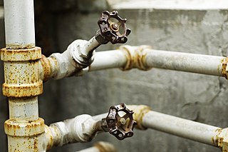
A valve is a device or natural object that regulates, directs or controls the flow of a fluid by opening, closing, or partially obstructing various passageways. Valves are technically fittings, but are usually discussed as a separate category. In an open valve, fluid flows in a direction from higher pressure to lower pressure. The word is derived from the Latin valva, the moving part of a door, in turn from volvere, to turn, roll.

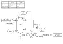
A schematic, or schematic diagram, is a designed representation of the elements of a system using abstract, graphic symbols rather than realistic pictures. A schematic usually omits all details that are not relevant to the key information the schematic is intended to convey, and may include oversimplified elements in order to make this essential meaning easier to grasp, as well as additional organization of the information.
Instrumentation is a collective term for measuring instruments, used for indicating, measuring, and recording physical quantities. It is also a field of study about the art and science about making measurement instruments, involving the related areas of metrology, automation, and control theory. The term has its origins in the art and science of scientific instrument-making.
Process engineering is the understanding and application of the fundamental principles and laws of nature that allow humans to transform raw material and energy into products that are useful to society, at an industrial level. By taking advantage of the driving forces of nature such as pressure, temperature and concentration gradients, as well as the law of conservation of mass, process engineers can develop methods to synthesize and purify large quantities of desired chemical products. Process engineering focuses on the design, operation, control, optimization and intensification of chemical, physical, and biological processes. Their work involves analyzing the chemical makeup of various ingredients and determining how they might react with one another. A process engineer can specialize in a number of areas, including the following:
Industrial process control (IPC) or simply process control is a system used in modern manufacturing which uses the principles of control theory and physical industrial control systems to monitor, control and optimize continuous industrial production processes using control algorithms. This ensures that the industrial machines run smoothly and safely in factories and efficiently use energy to transform raw materials into high-quality finished products with reliable consistency while reducing energy waste and economic costs, something which could not be achieved purely by human manual control.
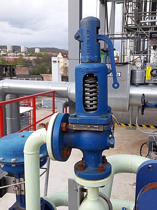
A relief valve or pressure relief valve (PRV) is a type of safety valve used to control or limit the pressure in a system; excessive pressure might otherwise build up and create a process upset, instrument or equipment failure, explosion, or fire.
In electrical signalling an analog current loop is used where a device must be monitored or controlled remotely over a pair of conductors. Only one current level can be present at any time.

Hydraulic machines use liquid fluid power to perform work. Heavy construction vehicles are a common example. In this type of machine, hydraulic fluid is pumped to various hydraulic motors and hydraulic cylinders throughout the machine and becomes pressurized according to the resistance present. The fluid is controlled directly or automatically by control valves and distributed through hoses, tubes, or pipes.

A chemical plant is an industrial process plant that manufactures chemicals, usually on a large scale. The general objective of a chemical plant is to create new material wealth via the chemical or biological transformation and or separation of materials. Chemical plants use specialized equipment, units, and technology in the manufacturing process. Other kinds of plants, such as polymer, pharmaceutical, food, and some beverage production facilities, power plants, oil refineries or other refineries, natural gas processing and biochemical plants, water and wastewater treatment, and pollution control equipment use many technologies that have similarities to chemical plant technology such as fluid systems and chemical reactor systems. Some would consider an oil refinery or a pharmaceutical or polymer manufacturer to be effectively a chemical plant.

A pilot plant is a pre-commercial production system that employs new production technology and/or produces small volumes of new technology-based products, mainly for the purpose of learning about the new technology. The knowledge obtained is then used for design of full-scale production systems and commercial products, as well as for identification of further research objectives and support of investment decisions. Other (non-technical) purposes include gaining public support for new technologies and questioning government regulations. Pilot plant is a relative term in the sense that pilot plants are typically smaller than full-scale production plants, but are built in a range of sizes. Also, as pilot plants are intended for learning, they typically are more flexible, possibly at the expense of economy. Some pilot plants are built in laboratories using stock lab equipment, while others require substantial engineering efforts, cost millions of dollars, and are custom-assembled and fabricated from process equipment, instrumentation and piping. They can also be used to train personnel for a full-scale plant. Pilot plants tend to be smaller compared to demonstration plants.
In chemical engineering, process design is the choice and sequencing of units for desired physical and/or chemical transformation of materials. Process design is central to chemical engineering, and it can be considered to be the summit of that field, bringing together all of the field's components.
A control loop is the fundamental building block of control systems in general and industrial control systems in particular. It consists of the process sensor, the controller function, and the final control element (FCE) which controls the process necessary to automatically adjust the value of a measured process variable (PV) to equal the value of a desired set-point (SP).
A process flow diagram (PFD) is a diagram commonly used in chemical and process engineering to indicate the general flow of plant processes and equipment. The PFD displays the relationship between major equipment of a plant facility and does not show minor details such as piping details and designations. Another commonly used term for a PFD is processflowsheet. It is the key document in process design.

Instrumentation is used to monitor and control the process plant in the oil, gas and petrochemical industries. Instrumentation ensures that the plant operates within defined parameters to produce materials of consistent quality and within the required specifications. It also ensures that the plant is operated safely and acts to correct out of tolerance operation and to automatically shut down the plant to prevent hazardous conditions from occurring. Instrumentation comprises sensor elements, signal transmitters, controllers, indicators and alarms, actuated valves, logic circuits and operator interfaces.
An isolation valve is a valve in a fluid handling system that stops the flow of process media to a given location, usually for maintenance or safety purposes. They can also be used to provide flow logic, and to connect external equipment to a system. A valve is classified as an isolation valve because of its intended function in a system, not because of the type of the valve itself. Therefore, many different types of valves can be classified as isolation valves.

In the process industry, chemical industry, manufacturing industry, and other commercial and industrial contexts, pipe marking is used to identify the contents, properties and flow direction of fluids in piping. It is typically carried out by marking piping through labels and color codes. Pipe marking helps personnel and fire response teams identify the correct pipes for operational, maintenance or emergency response purposes.
ISO 10628Diagrams for the chemical and petrochemical industry specifies the classification, content, and representation of flow diagrams. It does not apply to electrical engineering diagrams. ISO 10628 consists of the following parts:
In engineering, a symbolic language is a language that uses standard symbols, marks, and abbreviations to represent concepts such as entities, aspects, attributes, and relationships.
ISO 14617Graphical symbols for diagrams is a library of graphical symbols for diagrams used in technical applications. ISO 14617 consists of the following parts: